
Training & Testing
- Designed primarily for commercial and military environments
- PPC factory applied finishes in a range of RAL colours
- For internal and external applications
- Can be re used following a forced opening
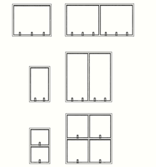
- Available in small, large and purpose made sizes
- Factory calibrated and adjustable after installation to accommodate increased operational requirements
| Frame Profile |
|---|
| Available as steel and aluminium profile |
| Minimum frame depth/wall thickness 70mm |
| Finishes |
|---|
| Factory applied Polyester Powder Coat |
| Available sizes |
|---|
| Min 500mm x 500mm |
| Max 1200mm x 2400mm |
| With additional units - indefinite |
| Overall thicknesses |
|---|
| Generally 70mm overall – other sizes by special order |
| Operating/Release pressures |
|---|
| Adjustable to order but min. 0.0065bar |
| Can be re set after installation for higher values |
| Options |
|---|
| Thermally broken |
| Weights |
|---|
| Frame profiles approx. 3kg/m - 15kg/m |
| Packing |
|---|
| Supplied in standard or international crates for dispatch |
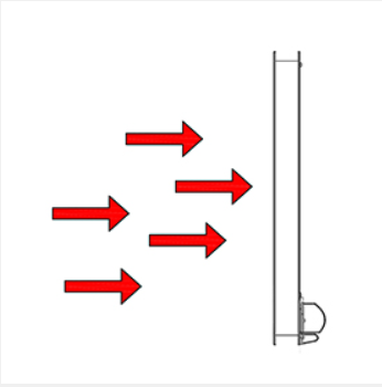
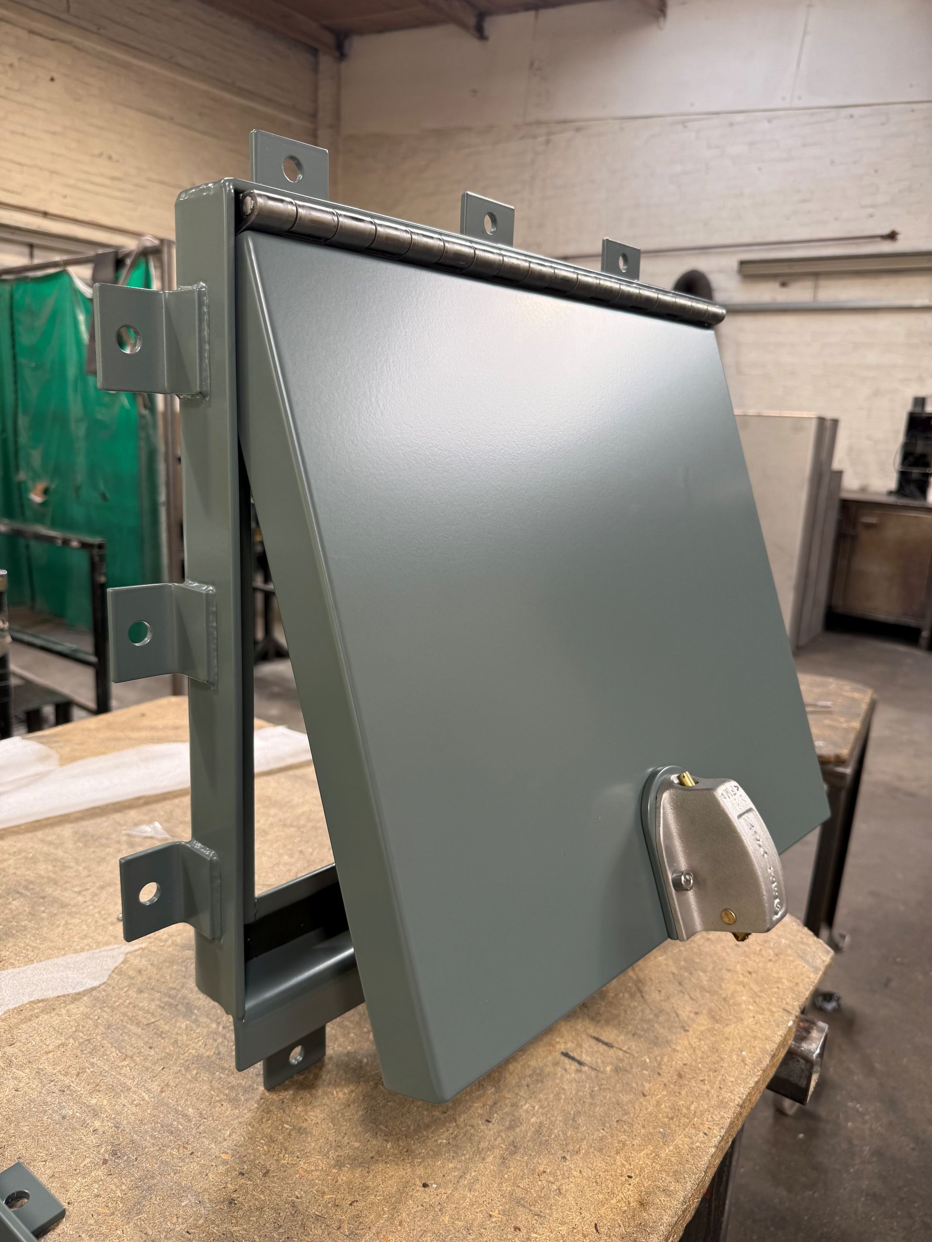
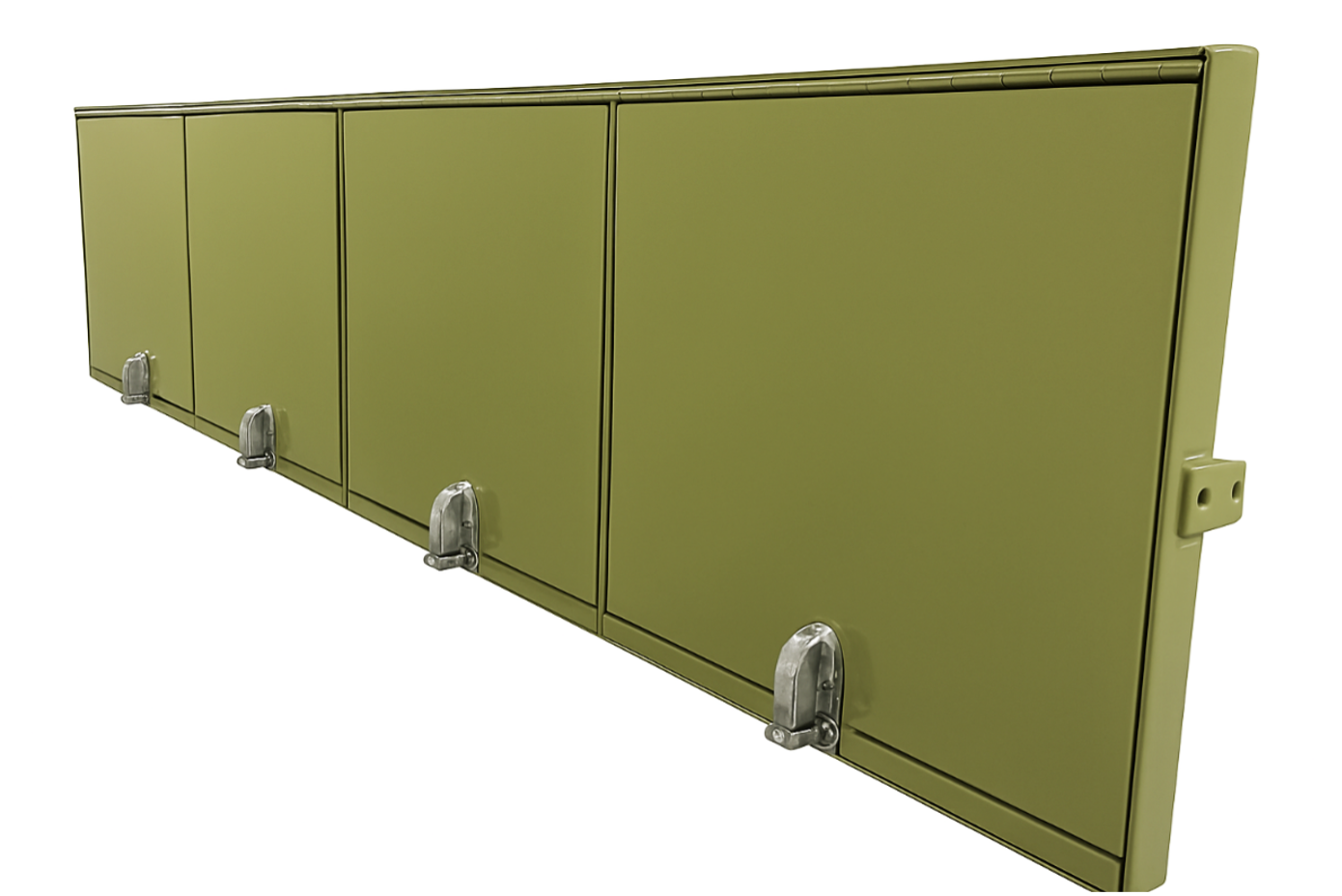
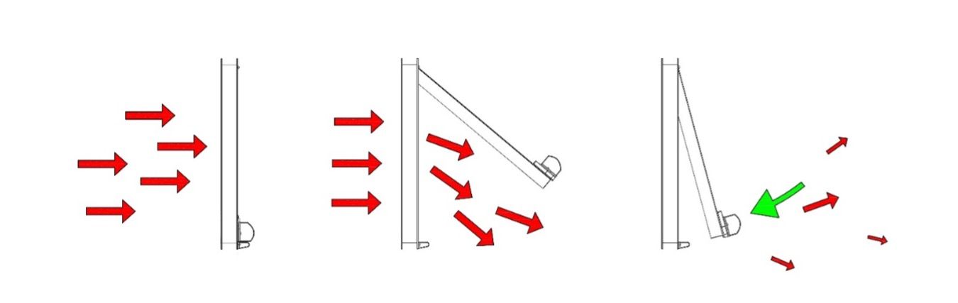
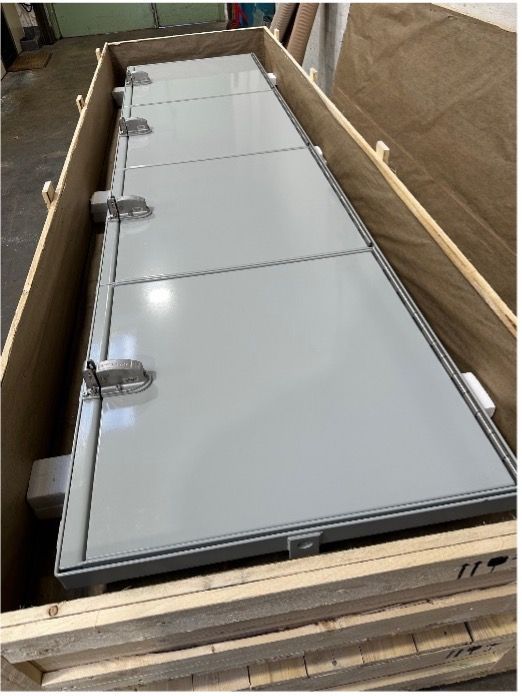
Top hinged vent in closed position
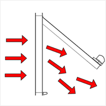
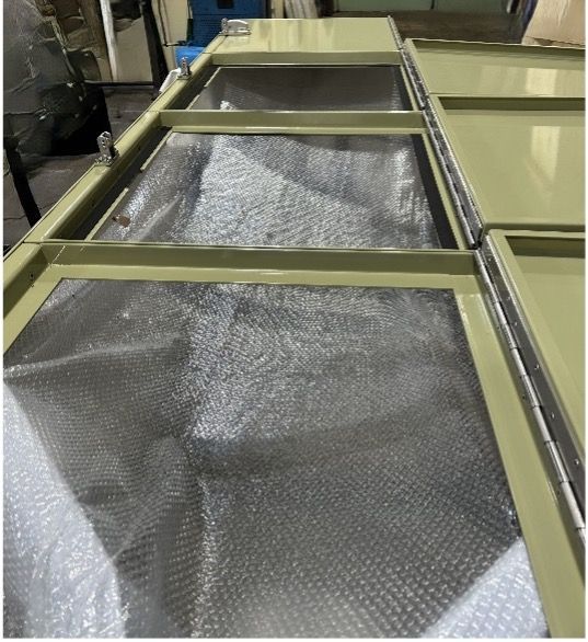
Top hinged vent opening under blast loading
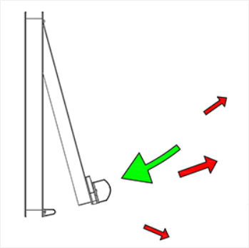
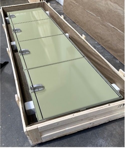
Top hinged vent can be re set after explosion
Available as both top and bottom hinged vent panel
Top hinged vent opening under blast loading
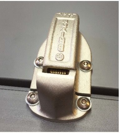
Model BBBV 1001
Spark proof adjustable latching
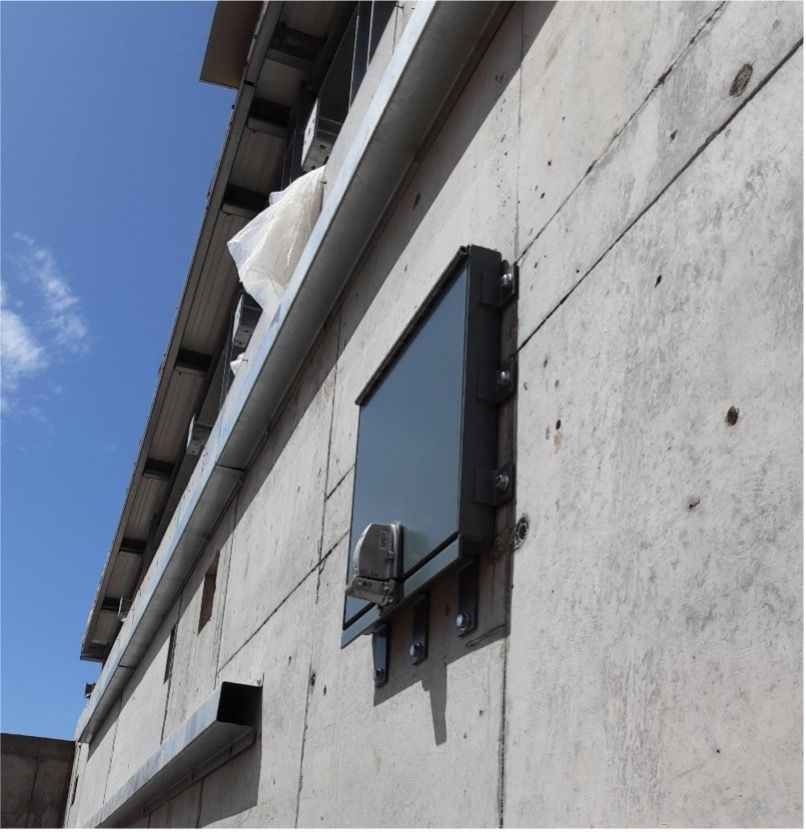
- Opaque solid infill panel
- Factory prepared for installation
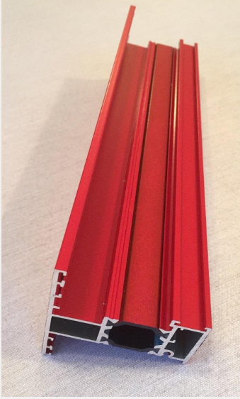
The Blast and Explosion Vents and Blast and Explosion Louvers are designed primarily to release overpressure from within a building or internal area. They are often required however to allow airflow at other times especially in the case of plant and machinery. The Blast and Explosion Louvres when fitted with the Blast Louver panel will do just that until such time as the pressure needs to be released. Pressure that is not aspirated through the Blast Louver will operate the release mechanism and the Blast and Explosion Louvre will release the panel and allow it to open.
The Blast and Explosion Vents and Louvers are also available with various types of solid insulated and also clear glazed panels. Allowing light transfer or not as the case may be. The frame system of both the Blast and Explosion Vent and Blast and Explosion Louver is thermally broken and is complimented with the use of thermally broken infill panels. A wide range of powder coat colour finishes is also available. Products are factory finished and packaged ready for dispatch.
The Blast and Explosion Vents can also be upgraded to provide ballistic protection. This helps protect against fragmentation which can be produced in commercial environments. As one example these Blast and Explosion Vents have been used to protect workers in areas such as the laboratory testing of high speed revolving parts or pressure pipework systems
Installation and Maintenance:
The unit is factory pre-assembled and after offering the frame into the prepared structural opening it is secured using proprietary frame or machine screw fixings
- The system can be sealed around its perimeter for weather tightness using proprietary sealants
- The system is lightweight and can sometimes remove the need to use other expensive handling equipment during installation
- After installation the unit can also be checked for operating release pressures and adjusted if necessary to accommodate increased or decreased blast/explosion threats from within the building
- Unless the previous blast/explosion has been particularly onerous for the unit it will simply close and is ready for operation – no need to replace the unit. Check that the unit has correctly re latched and is not damaged
- The unit is already factory calibrated ready for installation
- Installation is simple and reduces site cost
- The unit is lightweight and is often installed using one person
- The unit requires little maintenance. Check for correct operation, clean and check release pressure if required
- The centre panel of the unit is also available in clear finish to allow daylight transmission if required
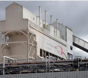
Typical Areas of Application
- Chemical Production
- Petroleum Industry
- Paint, Varnish Manufacturers
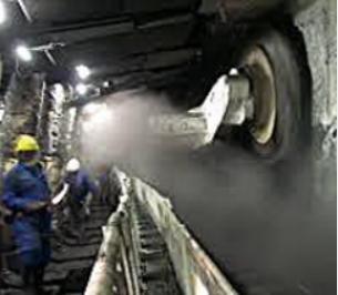
- Energy/ Mining Industry
- Co-Generation Plants
- Recycling Centres
- Sewage Treatment (by-product recycling)
- Automotive (air bag, mfg. Plant lines)
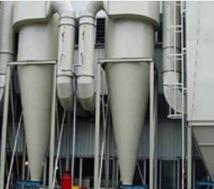
- Grinding/Pulverizing processes (airborne dusts)
- Ink Manufacturers
- Paper Process (solvent use/storage)
- Laboratory Test Facilities
- Hospitals (gas and/or flammable storage areas)
- Brewery Facilities (grain storage/processing)
- Fossil Fuel Plants (coal dusts)
- Food Processing (airborne dust)
- University Labs (chemical lab store rooms)
- Grain Milling Facilities (airborne dusts)
- Nuclear Power Stations
- Printing Companies (solvent use/storage)

Explosion Venting & Pressure Relief Panels
Here at Blast and Ballistics, we can provide blast vent panels, to protect against any major explosion. Our Explosion vents are made with the highest quality steel, for installation in Scanner Rooms, Post Rooms, Laboratories, Chemical Plants and Dust environments. Our pressure relief panels can be fitted into hatches and doors, custom made to your requirements.
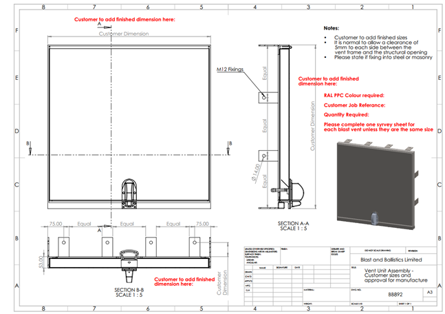
- When ordering please state finished overall width and height in millimetres.
- State the minimum required opening/release pressure. This will be factory set. Note – it may be necessary when stating this to consider local climatic conditions to allow for wind and other salient external effects which may exceed the release pressure and cause the vent to open when not required
- The release pressure can also be checked, calibrated and adjusted for higher or lower values even after installation
- Under normal operating conditions the vent can be closed after having been released and will be ready to operate again upon closure. It should be checked for correct operation however to ensure the blast pressure that the unit has vented has not been greater than anticipated and in consequence could have damaged or misaligned the vent unit.
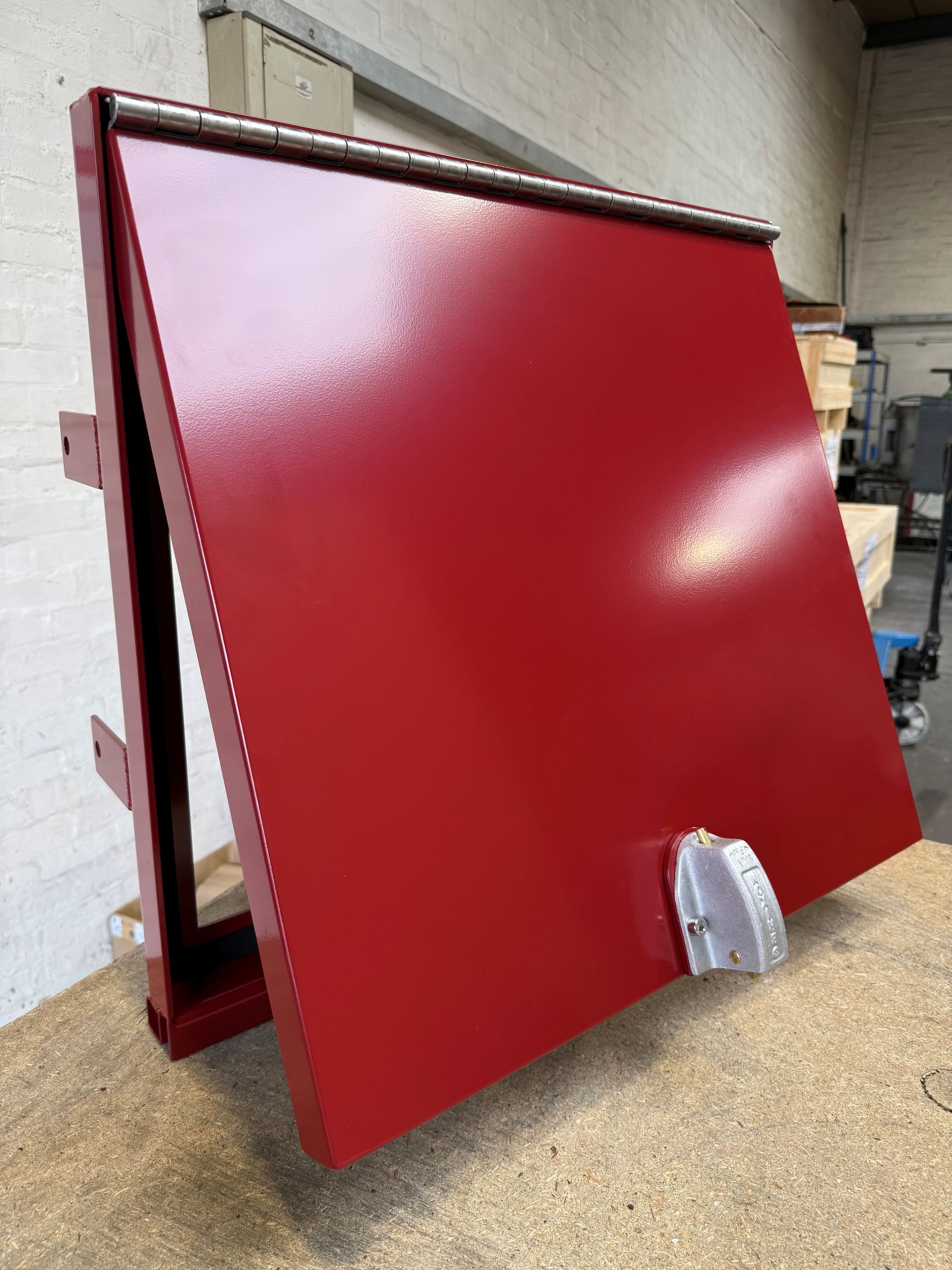
Explosion & Blast Release Vents
Technical Data Sheet
Product Description
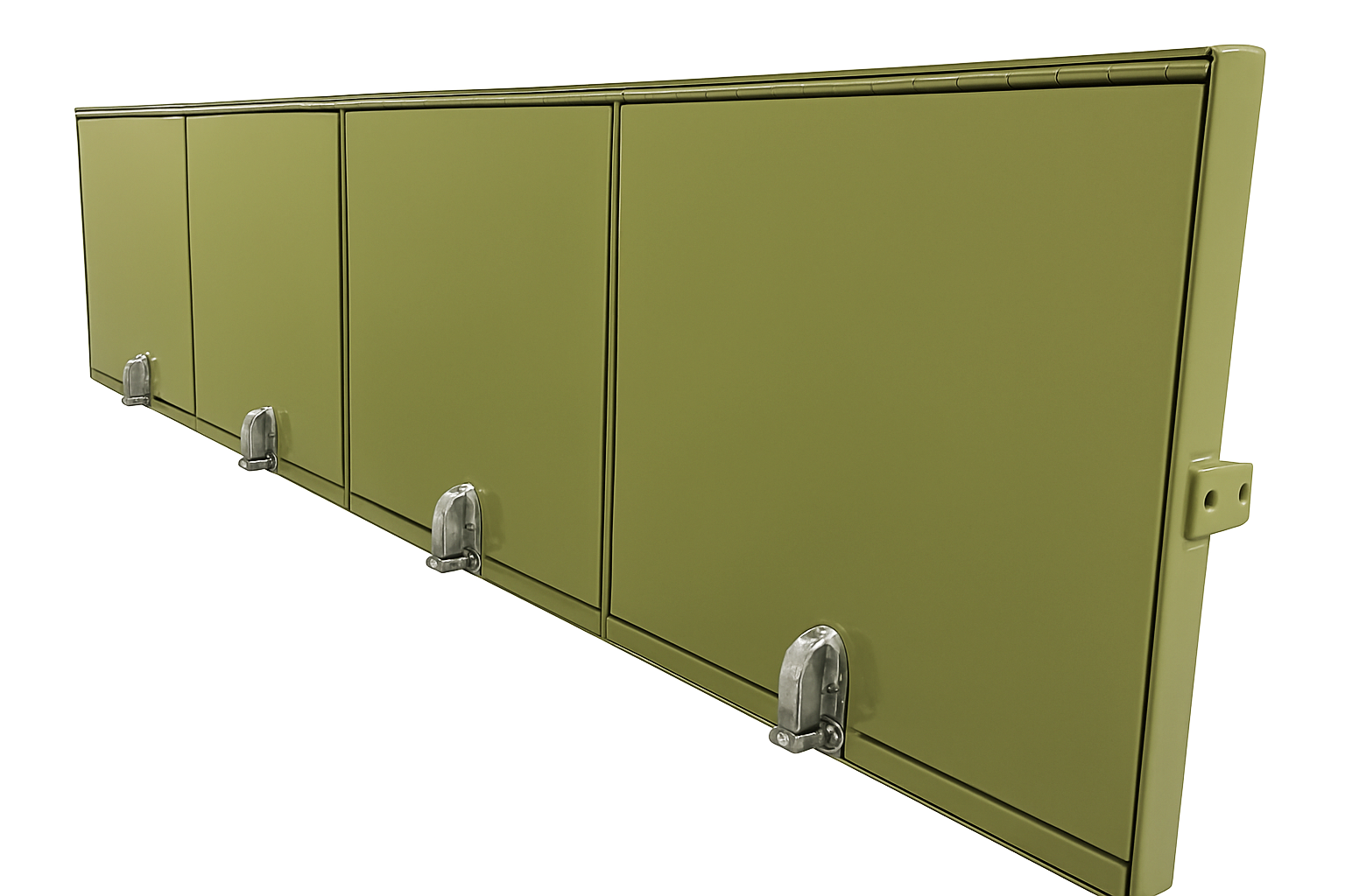
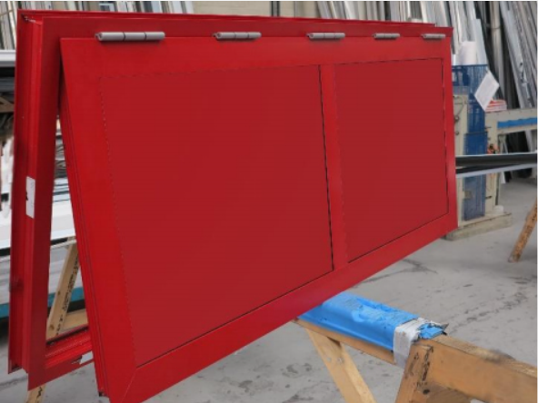
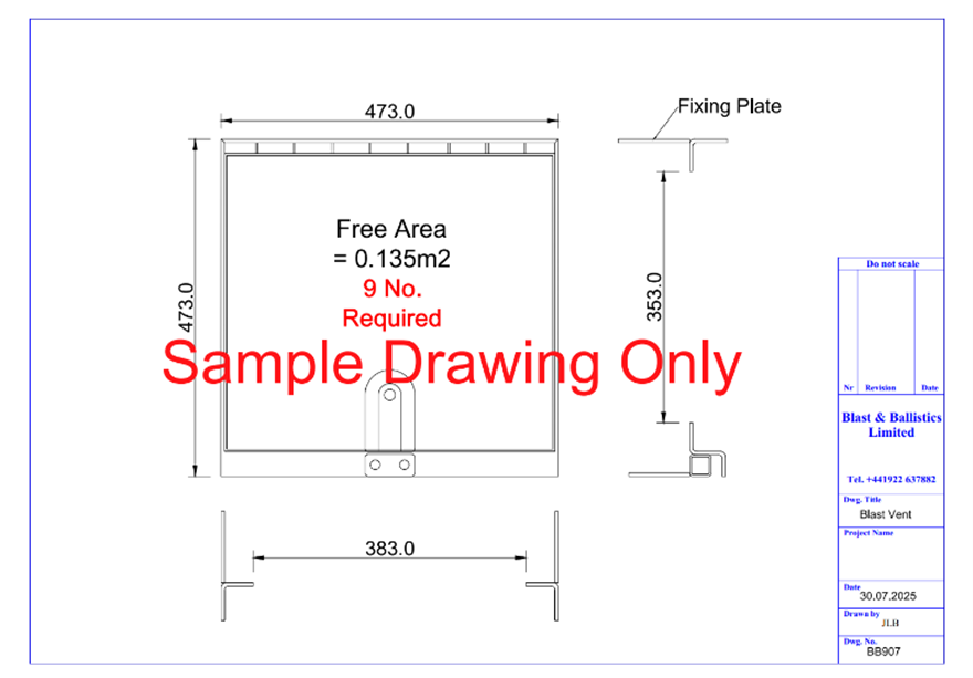
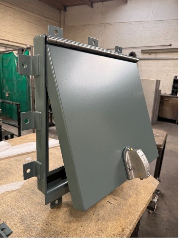
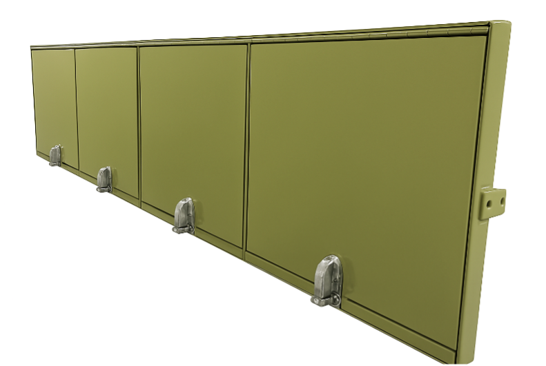
Our Blast Release Vents are bespoke products, manufactured to customer dimensions. The vents can be manufactured as single or multiple units and fixed into masonry or steel apertures.
Advantages
The vent can be re-used after an event by shutting the vent panel and setting the latch back in place. The vent incorporates a Brixon Release Latch which offers reliable and consistent performance, in-line with NFPA 68 guidelines.
Our Blast Release Vents are intended to protect the structural integrity of a building in the event of an explosion or overpressure event. The vent opens at a pre-determined and adjustable pressure to suit the customer’s individual requirements and applications.
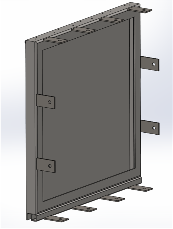
Features
- We use a Brixon Release Latch which is re-usable after an event (unless undergoing an unintended overpressure from catastrophic events) and allows for changes to release pressure for updated threats and applications.
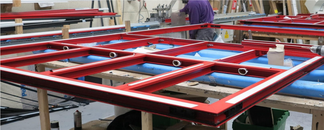
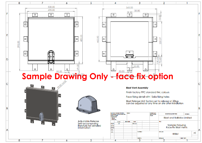
- The vents can be easily installed via fixing tabs attached to the frame. See below for details
- Available in RAL PPC finish and special finishes/colours on request.
Specification
| FRAME PROFILE |
|---|
| Manufactured from Aluminium, Steel, Stainless Steel |
| Minimum frame depth/wall thickness 80 - 100mm |
| Reveal and Face Fix options available |
| FINISHES |
|---|
| Factory finish RAL Polyester Powder Coat (PPC) or Mill Finish |
| Special finishes and colours available on request |
| AVAILABLE SIZES |
|---|
| Bespoke sizes available along with multiple units to allow for an indefinite effective size |
| WEIGHTS |
|---|
| Frame profiles approximately 3kg/m – 15kg/m |
| Vent panels approximately 12kg/m2 – dependant upon configuration and sizes |
| INSULATION |
|---|
| Available with insulation |
| Available without insulation |
| RELEASE VALUES |
|---|
| Minimum release value of 0.65kPa (0.0065 bar) |
| Factory set if required and can also be adjusted to customer’s required release pressure |
| The release can be easily adjusted on site to accommodate updated blast requirements |
| OVERALL THICKNESS |
|---|
| Generally 45mm overall and upwards depending upon wall details– other sizes by special order |
Areas of Application
· Chemical Production
· Petroleum Industry
· Paint, Varnish Manufacturers
· Energy/ Mining Industry
· Co-Generation Plants
· Recycling Centres
· Sewage Treatment (by-product recycling)
· Automotive (air bag, mfg. Plant lines)
· Grinding/Pulverizing processes (airborne dusts)
· Ink Manufacturers
· Energy Storage Systems (ESS)
· Industrial Processing Equipment
· Paper Process (solvent use/storage)
· Laboratory Test Facilities
· Hospitals (gas and/or flammable storage areas)
· Brewery Facilities (grain storage/processing)
· Fossil Fuel Plants (coal dusts)
· Food Processing (airborne dust)
· University Labs (chemical lab store rooms)
· Grain Milling Facilities (airborne dusts)
· Nuclear Power Stations
· Printing Companies (solvent use/storage)
· Gas/Vapour Handling Equipment
· Dust Collection Systems
Additional Information
Selecting a Release Pressure
State the minimum required opening/release pressure. This can be factory set. Note – it may be necessary when stating this to consider local climatic conditions to allow for wind and other salient external effects which may exceed the release pressure and cause the vent to open when not required.
Under normal operating conditions the vent can be closed after having been released and will be ready to operate again upon closure. It should be checked for correct operation however to ensure the blast pressure that the unit has vented has not been greater than anticipated and in consequence could have damaged or misaligned the vent unit or an uneven or quasi static pressure wave may have twisted the unit.
Fitting Instructions
Preparing the unit for installation – single and multi-unit system
The vent panels and outer frame are usually delivered as a single item. Unless specifically requested otherwise, the outer frame will already be prepared on site for fixings. Ensure that the fixings that are going to be used are aligned with suitable fixing points in the wall aperture. Do not fix into thin sheet metal or cladding materials.
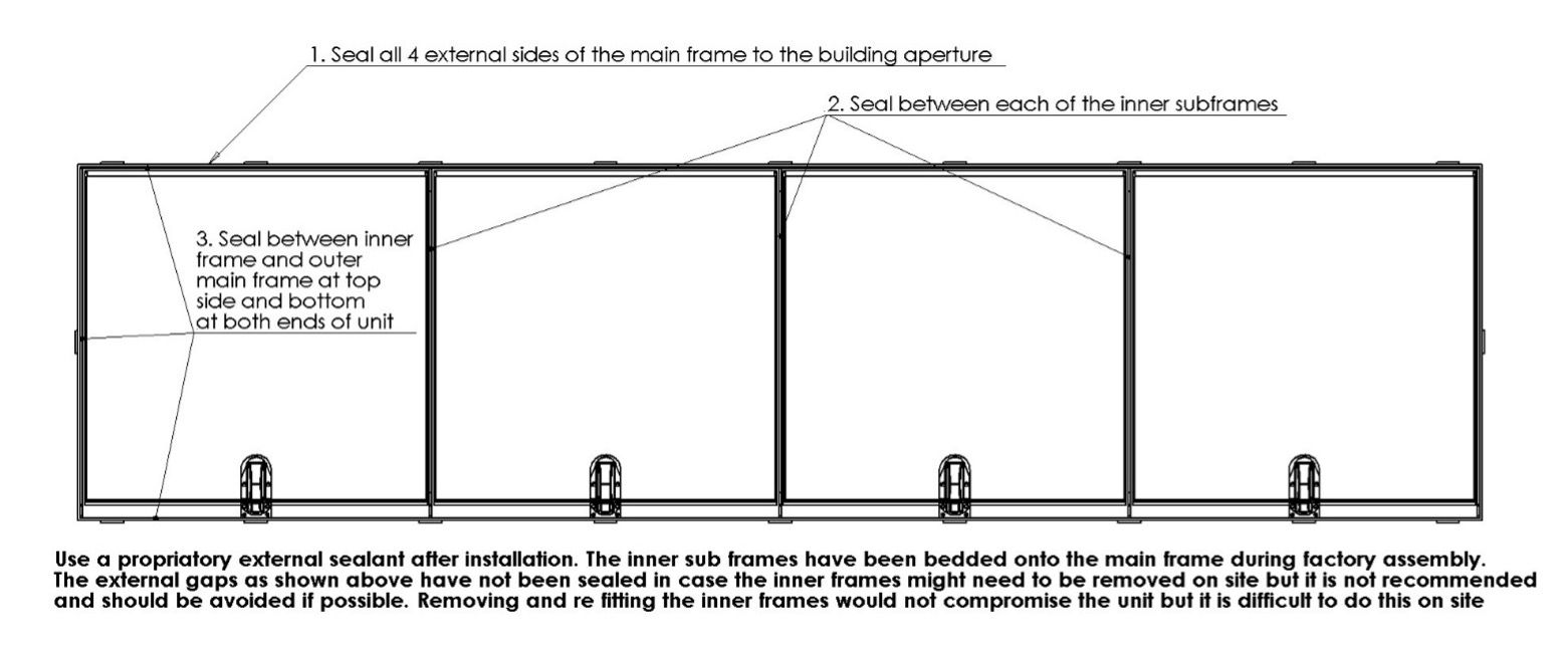
When the unit is fixed into the wall aperture the vent panels should open and close freely. Ensure that the unit is not fitted in twist and is well packed around each fixing point to avoid stretching or compressing the clearances around the hinged panels. These will have been factory checked before dispatch. The fixing tabs around the outer main frame are factory prepared for fixings. They project inwards (or sideways for surface fixing) enabling the whole assembly to be installed without the need to dismantle components. The face fix option is to be installed on the surface of the wall construction.
The assembly can be broken down into smaller components, but this is not recommended if it can be avoided. Realigning components on site is much more difficult than in a factory environment. In addition, the inner frame assemblies are sometimes bedded on sealant, and this would have to be broken and reinstated making the entire process arduous.
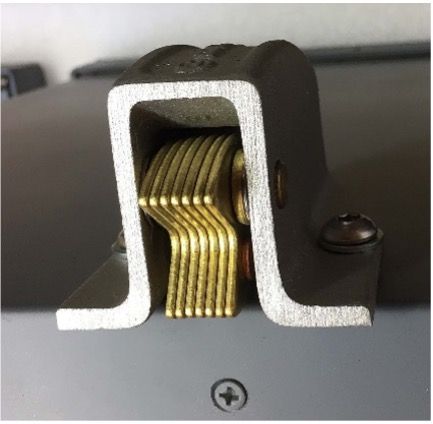
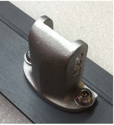
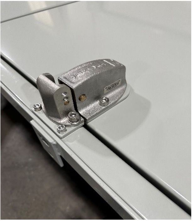
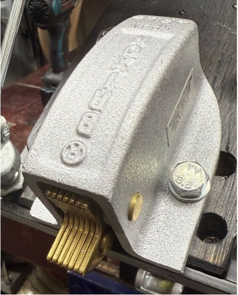
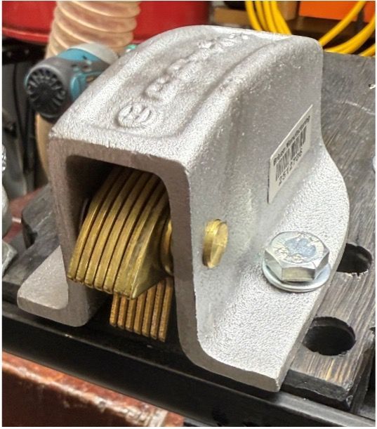
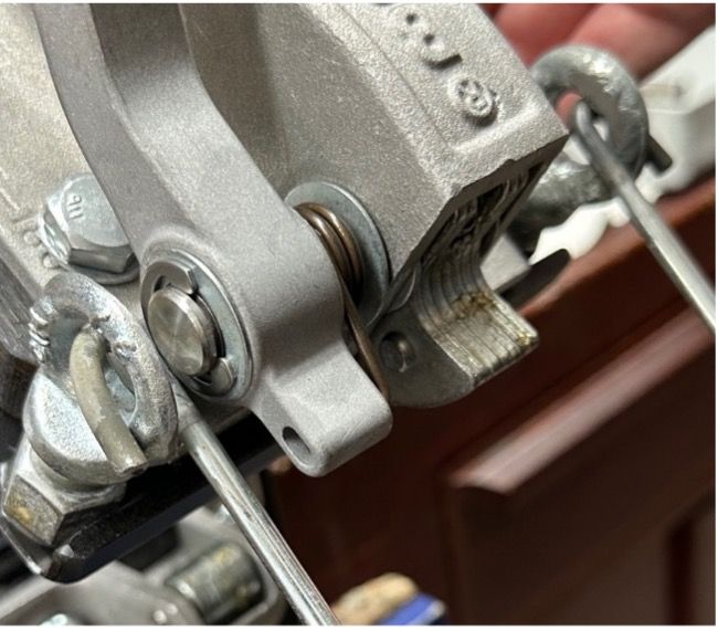
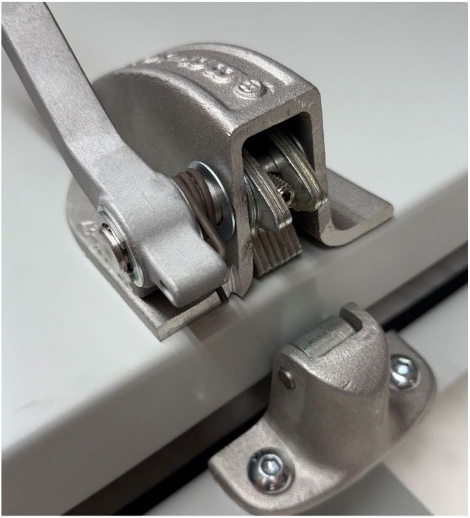
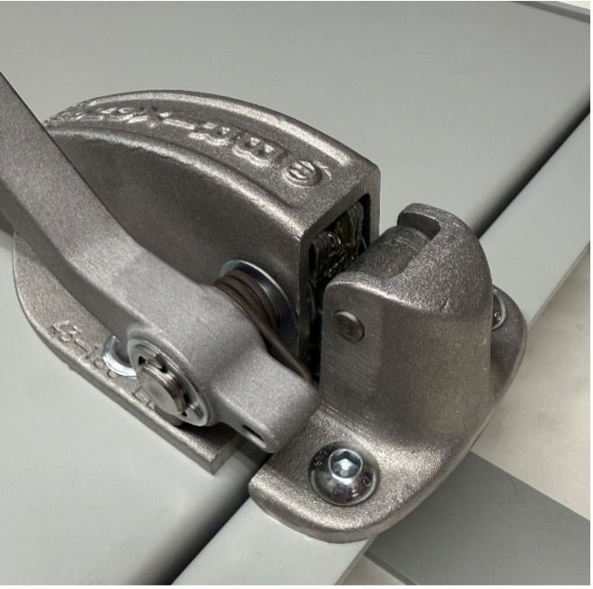
The Pressure Release Mechanism is a two-part assembly consisting of the Pressure Release Main Body and the Pressure Release Strike. These are factory fitted but can be easily removed for service and can also be adjusted to vary the point at which the vents will open. Adjustment instructions for this unit are shown later in this document. Regularly check and grease the release unit when in use.
If the Release Vents have been supplied prime painted only, then it may be preferred to remove these units before top coat on site. Instructions for removal are detailed below. However, if the units are not intended to be removed then the moving components/contact points (brass coloured elements) can be greased in situ with a proprietary grease. This is important to ensure correct operation of the Release Unit. If the Vent Units are supplied pre-finished in top coat paint or PPC then the Release Units will be factory lubricated before dispatch when requested. Applying lubricants to prime finish products may result in grease contaminating primer coats and subsequently compromising the final top coat. Mill finish or PPC factory finish is not affected.
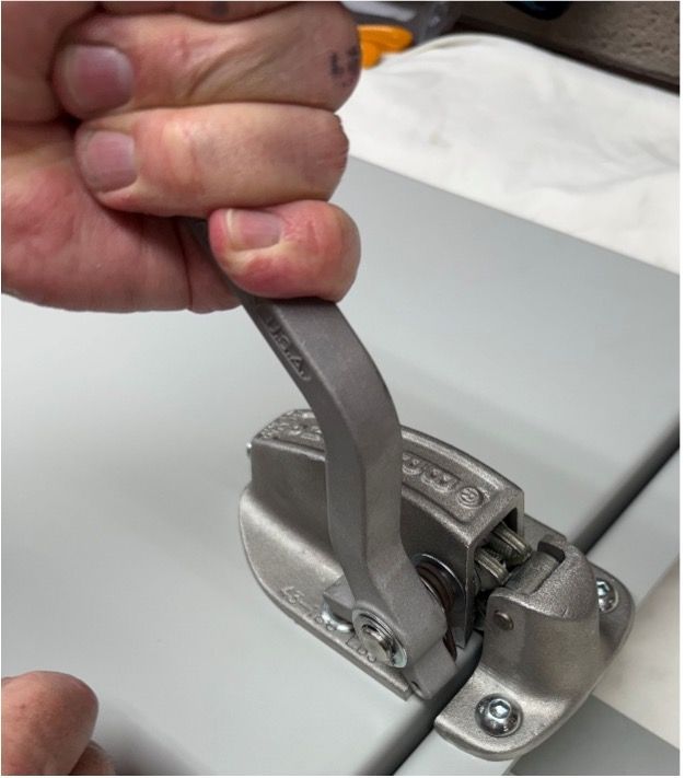
Note: Always check that the latch is in the open position when closing the vent panel. If not, manually move the latch into the correct position. See images left.
Hinges
Hinges are factory fitted and are fabricated in stainless steel. They require little maintenance other than lubrication with general purpose oil after installation. Lubricating the hinge on a regular basis can also be carried out at the same time as regularly re-applying fresh grease to the Release Mechanism. Regular checking and maintenance is very important. Check all fixing and retaining bolts especially after an event.
Reveal Fix
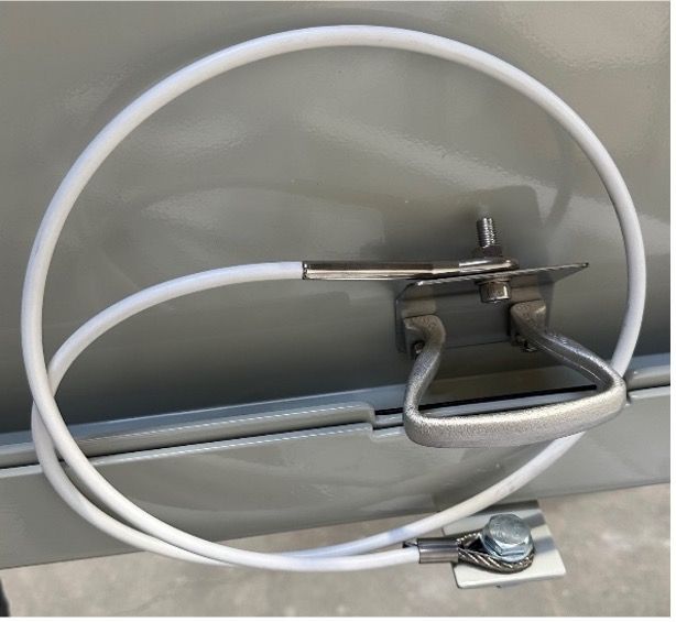
The cable restraint is fitted last, after the whole assembly has been installed into the building aperture. This is a steel wire cable wrapped in a plastic sheath to minimise scuffs and scratches to the local paint finish.
Fit one end to one of the outer assembly fixing bolts (suitable for M12 fixings) and the opposite end to the angled plate which is bolted through underneath the inner pull handle. This will accept an M8 nut and bolt with washer.
Loop the cable generally as shown and test the panel to ensure that the cable does not snag on anything when opened.
The cable restraint is intended to minimise the travel of the opening vent flap and also act as a further restraint should the panel begin to fail due to excessive overpressure. It is not a guaranteed solution to the potential of catastrophic failure due to excessive overpressure or resultant quasi static forces often resulting from internal blast and gas pressures.
Reveal Fix
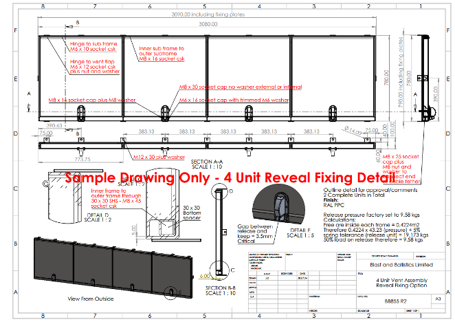
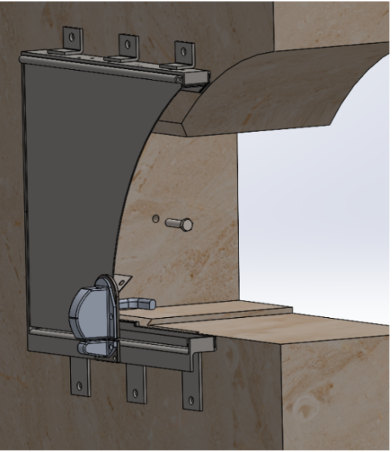
For a reveal fix blast vent, the cable restraint needs to be attached as indicated below.
1. One end of the cable is to be attached to the supporting plate on the inner face of the vent panel with the nut and bolt provided.
2. The other end is to be attached to one of the fixing tabs as shown below.
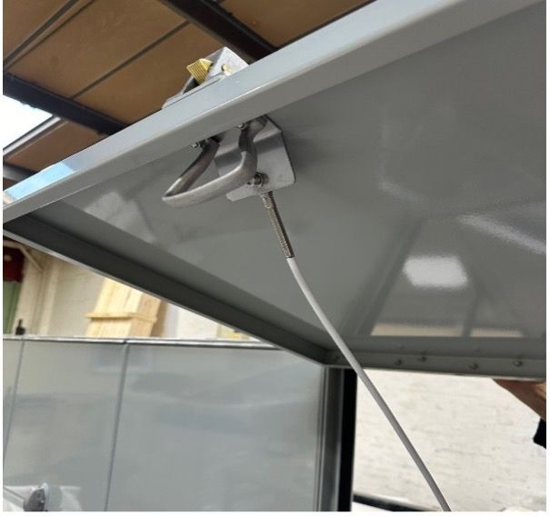
For a face fix blast vent, the cable restraint needs to be attached at one end as shown in bullet point 1 and the associated image.
The other end of the cable must then be attached to the inside of the reveal as illustrated left.
Attach the restraint cable here, held in place with nuts and bolts.
General Notes
Under normal operating conditions the blast vent may open and close many times and each time the unit should be checked for damage or distortion which can always occur should the internal blast loading be more onerous than anticipated or the unit undergo a non-uniform blast load.
Check that the vent itself has not become loose around its fixings into the wall, that all screws and fixing bolts are tight and that the vent itself closes and seats into the outer frame. Also look at the Release Unit clearances and adjustments as detailed separately. Although not a direct component of the Pressure Release Vent it is always worth checking that all mastics and sealants are intact and show no sign of degradation either following an incident or as just part of the maintenance regime. All of these points should be included within the company maintenance programme.
Finally, after installation and as ongoing maintenance, clean the unit with a non-abrasive proprietary cleaning agent to protect the surface coating of the units. Continue to check the surface finishes regularly and reinstate immediately to prevent rust forming or debris collecting and trapping water.
Note: Local risk assessments should always be undertaken when installing blast vents to protect both members of Staff and also the General Public. A Blast Vent can open suddenly and without prior warning when releasing internal blast pressures. It is also possible that parts of the unit under higher than anticipated blast pressures can break free. Insufficient venting area of the building can also increase localised pressure on release vents. Any of these types of instances can cause injury and it is important to provide sufficient space where blast vents are installed to accommodate and mitigate this potential for injury. Consideration should be given to incorporating warning signs and suitably cordoned areas as just one means of providing personnel protection.
Use signage to warn persons that there is the potential of an explosion in the immediate vicinity.
In addition to the vent unit suddenly opening and releasing gas pressure there is always the risk of catastrophic failure of the vent components and other building items such as windows, doors, roof and walls. Any of these items can produce fragmentation and become a potential hazard. It is always advisable to carry out an independent risk and product risk assessment in these areas. This is very important.
Adjustment & Latch Selection Help – Latch Release Force
Brixon latches are designed to operate under a wide variety of conditions with a variety of options available to suite particular purposes. The user must insure that the latches are appropriate for the particular application. Any questions regarding model selections should be referred to the factory.
It is recommended that the latch release force be adjusted prior to mounting when the internal components are visible. The pressure setting should allow the latch to open at an internal pressure slightly higher than that encountered under normal operation circumstances. Caution: Factory Mutual Global requires that latches open at a maximum internal pressure of 50 lbs/ft2 (244.1 kg/m2), while NFPA (National Fire Protection Association) recommends 30 lbs/ft2 (146.5 kg/m2): in general, the lowest practical setting should be used
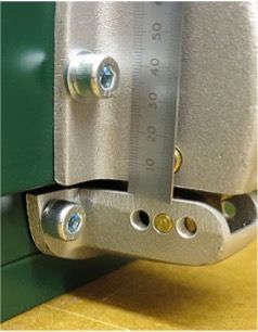
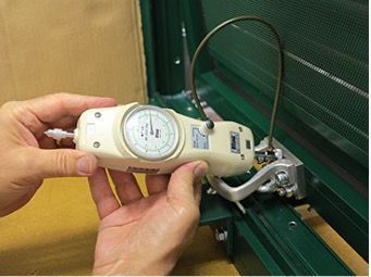
Note: Precise pressure adjustment is not possible due to the location of the strike, the amount of gasket compression, friction, etc. The listed values are a guide only, and if the release pressure is critical, the pressure must be measured directly at the door after installation for more accuracy. The estimated variance is plus or minus 2 full turns.
Note: Precise pressure adjustment is not possible due to the location of the strike, the amount of gasket compression, friction, etc. The listed values are a guide only, and if the release pressure is
critical, the pressure must be measured directly at the door after installation for more accuracy. The estimated variance is plus or minus 2 full turns.
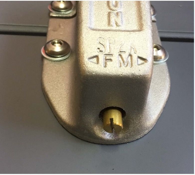
To adjust, have the latch in the door closed position (see illustration above), wherein one rivet which holds the laminated cam together is exposed.
Turn the adjusting screw counter-clockwise to its loosest position, making sure that the square nut does not come off the ball pin and the nut has full thread engagement. Using the Latch Release Force Adjustment Chart (below) as a guide, tighten the adjusting screw clockwise a half turn at a time until the desired pressure setting is reached. It should be possible to feel the adjusting screw slipping into the relaxed position at each half turn. For example, if you wanted 107 lbs. pressure setting on a #4 latch, you would tighten the adjusting screw 10 half turns (10 x 4.935) + (58 lbs. min.) = 107 lbs.
If the latch is mounted, adjustment can be made by turning the adjustment screw to its tightest position and backing off to the desired setting. Latches can be factory adjusted upon request for additional cost. For example, if you wanted 107 lbs pressure setting on a #4 latch, you tighten the adjustment screw clockwise to its maximum position. Then you would loosen the adjustment screw counter-clockwise 36 half turns {285 lbs max. - (36 x 4.935)} = 107 lbs
| Latch Model | Minimum | Maximum | Pressure (lbs) Per Turn | Pressure (lbs) Per ½ Turn | Full Turns Available |
|---|---|---|---|---|---|
| 1 | 3.9 | 17 | 1.50 | .75 | 8.75 |
| 91 | 3.9 | 17 | 1.5 | 0.750 | 8.75 |
| 2 | 10 | 45 | 2.50 | 1.250 | 14 |
| 3 | 43 | 180 | 5.96 | 2.980 | 23 |
| 83 | 43 | 180 | 5.96 | 2.980 | 23 |
| 93 | 43 | 180 | 5.96 | 2.980 | 23 |
| 4 | 58 | 285 | 9.87 | 4.935 | 23 |
| 84 | 58 | 285 | 9.87 | 4.935 | 23 |
| 94 | 58 | 285 | 9.87 | 4.935 | 23 |
| Latch Model | Minimum | Maximum | Pressure (lbs) Per Turn | Pressure (lbs) Per ½ Turn | Full Turns Available |
|---|---|---|---|---|---|
| 1 | 1.8 | 7.7 | 0.67 | 0.0335 | 8.75 |
| 91 | 1.8 | 7.7 | 0.67 | 0.0335 | 8.75 |
| 2 | 4.5 | 20.4 | 1.14 | .570 | 14 |
| 3 | 19.5 | 81.6 | 2.70 | 1.350 | 23 |
| 83 | 19.5 | 81.6 | 2.70 | 1.350 | 23 |
| 93 | 19.5 | 81.6 | 2.70 | 1.350 | 23 |
| 4 | 26.3 | 129.3 | 4.48 | 2.240 | 23 |
| 84 | 26.3 | 129.3 | 4.48 | 2.240 | 23 |
| 94 | 26.3 | 129.3 | 4.48 | 2.240 | 23 |
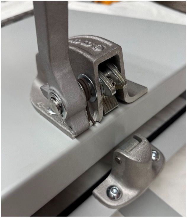
The latch and strike assembly must be securely mounted so that the cam is centred on the strike roller and the assembly is perpendicular to the door-frame line. The distance between the latch and strike housing should be 1/16” to 3/32” for #91 models and #1 models (#1 model no longer for sale).
The distance between the latch and strike is 1/8” to 5/32” for the #2 model. #3, #83, #93, #4, #84 and #94 latches and strikes should be spaced 1/8” to 3/16” apart.

This is most likely to happen when the door is slammed (excessively) and/or the latch mechanism is dirty or corroded. In this event, the door may be more difficult to open, either by hand or in the event of an explosion. It is also a warning that maintenance is required and that a hazardous situation exists.
Because of the rather large tolerances involved in casting, each latch/strike combination must be individually aligned, and alignment must be rechecked whenever latches are replaced to avoid possible malfunctions as listed below.
In mounting the 3H, 83H, 93H, 4H, 84H, 94H or 4HD latches, it may be found that the handle stops interfere with the mounting nuts, when studs are used. If you intend to use studs, consult the manufacturer for information on modifications that may be necessary.
Operation
The Brixon latch operates in a manner similar to a toggle switch. When the door and latch are in the closed position, the latch will hold the door closed unless enough pressure is applied to compress the spring sufficiently to cause tripping of the cam into the open position. When the cam is in the open position, the door is free to open.
Closing is essentially the reverse of the above, with the force to reset the cam being supplied by the closing door.
The forces required for operation depend upon the settings of the latch (see ADJUSTMENT) - The higher the setting and the larger the latch, the greater the required force.
The recommended procedure for closing a door equipped with the 3H, 83H, 93H, 4H, 84H or 94H latches is to fold the handle back immediately prior to closing or, better, to first open and then close the handles. When folding the handles back, the cam should remain in the “open” position (illustration #4). If for any reason the cam is in the “closed” position (illustration #5) while the door is open, the latch and/or its mounting is defective, and the door would rebound open instead of latching..
In the event of an explosion, the latch will begin to open when the internal pressure equals the setting of the latch. However, due to inertia in the latch-door system, there will be a slight delay between application of pressure and the opening of the door (See NFPA No. 68). This might allow a considerable pressure build-up, depending upon the oven size, type, and amount of material
exploding, and the time lag involved. In the event of an explosion of maximum violence, the effectiveness of the latches is reduced. However, most explosions are not of maximum violence (FM Global Approval Guide, 1998 8-
Summary & Cautions For Operators
- Violent slamming is potentially hazardous and must be avoided.
- For reasons listed above, the door may not latch when closing; beware of rebound.
- Keep clear of the arc of the door.
- Keep clear of the operating parts of the latch and handle, particularly the laminated cam, strike roller, both ends & handle stop of the heavy duty handles, and the stops for standard 3H, 4H, 83H, 84H, 93H, & 94H handles.
Factory Setting of The Release Latch:
It is always more convenient for the customer to have the release latches factory set at the onset
Frequently Asked Questions
What are blast and explosion release vents?Title or Question
Blast and explosion release vents are pre-engineered roof units designed to open at a set internal pressure and safely vent an explosion from inside a building. By giving the over-pressure somewhere controlled to go, they reduce structural damage and the risk of injury in rooms where flammable gases, vapours, dusts or other explosive atmospheres may be present.
How do your blast relief roof vents work?
Each vent has a lightweight, insulated top panel that is held in place by FM Approved release fixings. When the internal pressure reaches the pre-set value, the fixings release and the lid lifts clear, allowing the blast pressure and gas to escape. The panel is tethered with steel restraint cables to help control where it travels, and the release pressure can be tuned to suit both the blast regime and local climatic conditions
Which industries typically use explosion relief vents?
Blast relief roof vents are widely used wherever there is a risk of internal deflagration, including:
- Petroleum, energy and mining facilities
- Chemical and hydrogen applications
- Breweries and food processing plants
- Automotive and co-generation plants
- Lithium battery storage, hospitals and university laboratories
In many of these environments, roof vents complement other measures such as blast louvres and frangible blow-out panels to complete the safety strategy
What standards do your blast relief vents comply with?
Blast & Ballistics explosion relief roof vents are designed and manufactured with reference to leading industry standards, including:
FM Global Loss Prevention 1-44 (Venting Class of Work 4440)
NFPA 68 – Standard on Explosion Protection by Deflagration Venting
They can also be configured to help meet ATEX-related requirements where applicable, giving specifiers confidence that the venting solution follows recognised, up-to-date guidance
How many blast vents do I need and where should they be installed?
The number, size and position of blast relief vents are determined by your blast engineer, based on the building volume, construction and expected explosion characteristics. In simple cases, a single vent located directly above the main hazard may be sufficient; in more complex rooms, multiple vents are often used to share the load and cope with uneven internal pressure patterns. Positioning is critical: vents should be located so the blast wave can act as uniformly as possible on the lid, ensuring it opens quickly and vents the space effectively.