
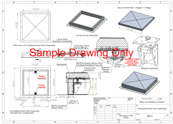
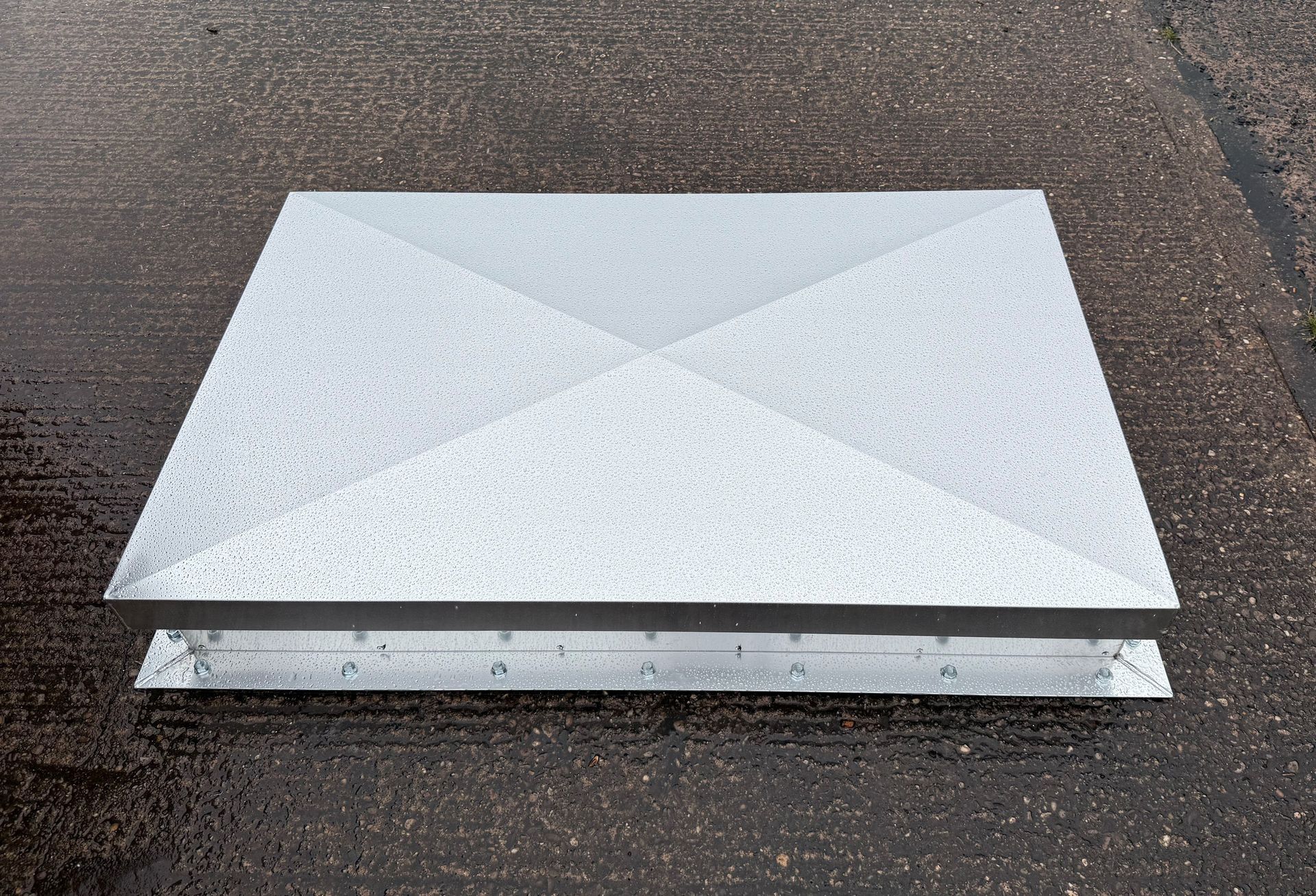
Blast / Explosion Relief Roof Vents
DOWNLOAD TECHNICAL DATA SHEET
Explosion And Blast Relief Roof Vents
- Used in high-risk industries and for applications prone to internal explosions or detonations
- The product is an ideal solution for areas where explosive materials such as gaseous, flammable substances or dust particles are stored and venting is only possible from the roof area.
- The product uses FM Approved Blast Release Bolts which are manufactured to provide an accurate and consistent release. We can accomodate all release pressures, please contact us for further details.
- Available in Mill Finish as standard or factory PPC finish to a standard RAL colour. Special finishes available on request.
Product Description
Explosion And Blast Relief Roof Vents allow for the overpressure following an explosion to be vented efficiently. This is ideal for food and chemical processing and commercial environments where the roof is the most appropriate location to vent. The product is made to order and manufactured to customer's required dimensions, release pressure and roof construction.
Please get in touch to discuss specific project requirements.
Advantages
By using FM Approved Blast Release Bolts, we can accomodate a wide range of release pressures which are dictated by the customer's reqiorements. For further information on FM Approval Bolts, please refer to the FM Approval Guide for further information.
The product also follows NFPA 68 Guidlines by providing a means to safely release and vent pressure from deflagrations. Whilst there are further considerations to be made for the location, suitability and quantity of vents, the product allows for effectively venting overpressure and is a key component of NFPA 68 Guidelines.
Features
- Available in Mill Finish as standard with Factory PPC and special finishes available upon request.
- Suitable for different roof constructions, e.g masonry / steel construction.
- Adjustible curb / vertical wall height.
- Bespoke product manufactured to customer dimensions and required release value.
- Use of FM Approved Blast Release Bolts.
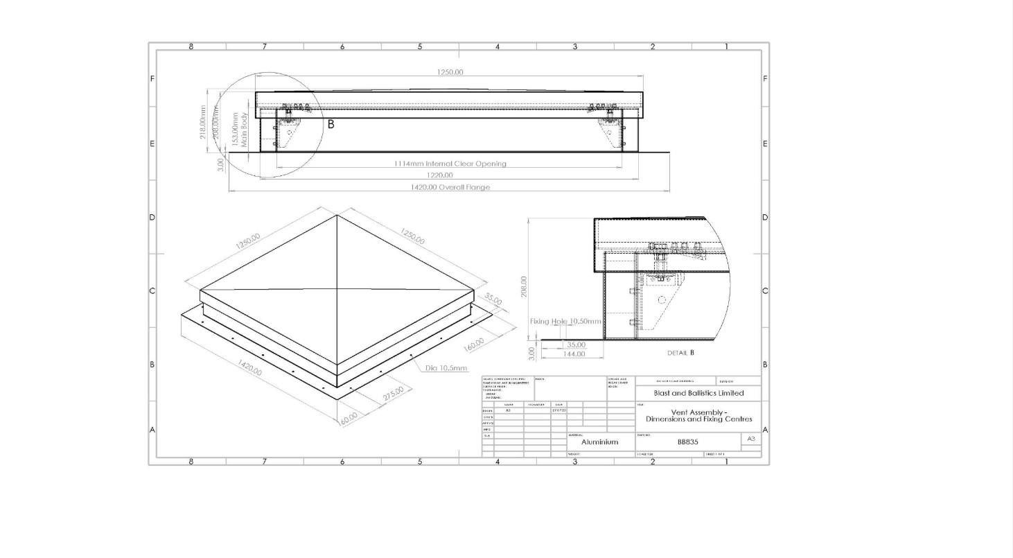
| PROFILE |
|---|
| Fabricated Aluminium Base and Top Assembly |
| Main Body 153mm high |
| Top Panel 62mm high |
| FINISHES |
|---|
| Mill Finish Aluminium as standard |
| Factory PPC Finish to a standard RAL colour |
| Special finishes available on request |
| AVAILABLE SIZES |
|---|
| Standard size nominal 1220mm x 1220mm |
| Bespoke sizes made to order |
| Overall finished size - add 249mm on width and height |
| WEIGHTS |
|---|
| Top lid assembly 9.80kg/m2, meeting FM Global Approved 1-44 |
| STANDARDS AND REFERENCES |
|---|
| FM Global Loss Prevention 1-44 Rev 2023 Venting Class of Work 4440 Vent Releasing Product |
| Manufactured with regard to NFPA 68 guidelines - design, location, installation, maintenance of Venting (Standard on Explosion Protection by Deflagration Venting 2023) |
| THERMAL PROPERTIES |
|---|
| All panels are insulated with minimum 50mm EPS70 insulation FR in Mill Finish |
| All panels are insulated with minimum 50mm Rockwool insulation FR if required in PPC Finish |
| EXPLOSION RELEASE VALUES |
|---|
| FM Approved Release Bolts are manufactured in a range of values. EXA 74, EXA 76, EXA 79, EXA 84 - and the Blast Release Roof Vents use these in various combinations to provide the Blast Release value that is required in each application. |
| TOP RELEASE PANEL EXPANSION ALLOWANCE |
|---|
| Explosion Release Assembly Units incorporate expansion and contraction mechanisms |
| FIXING HOLE POSITIONS |
|---|
| See drawing - Prepared to industry standard to accept up to 20 fixings or as detailed by customer |
| RESTRAINTS |
|---|
| Restraint cables included |
| SHIPPING |
|---|
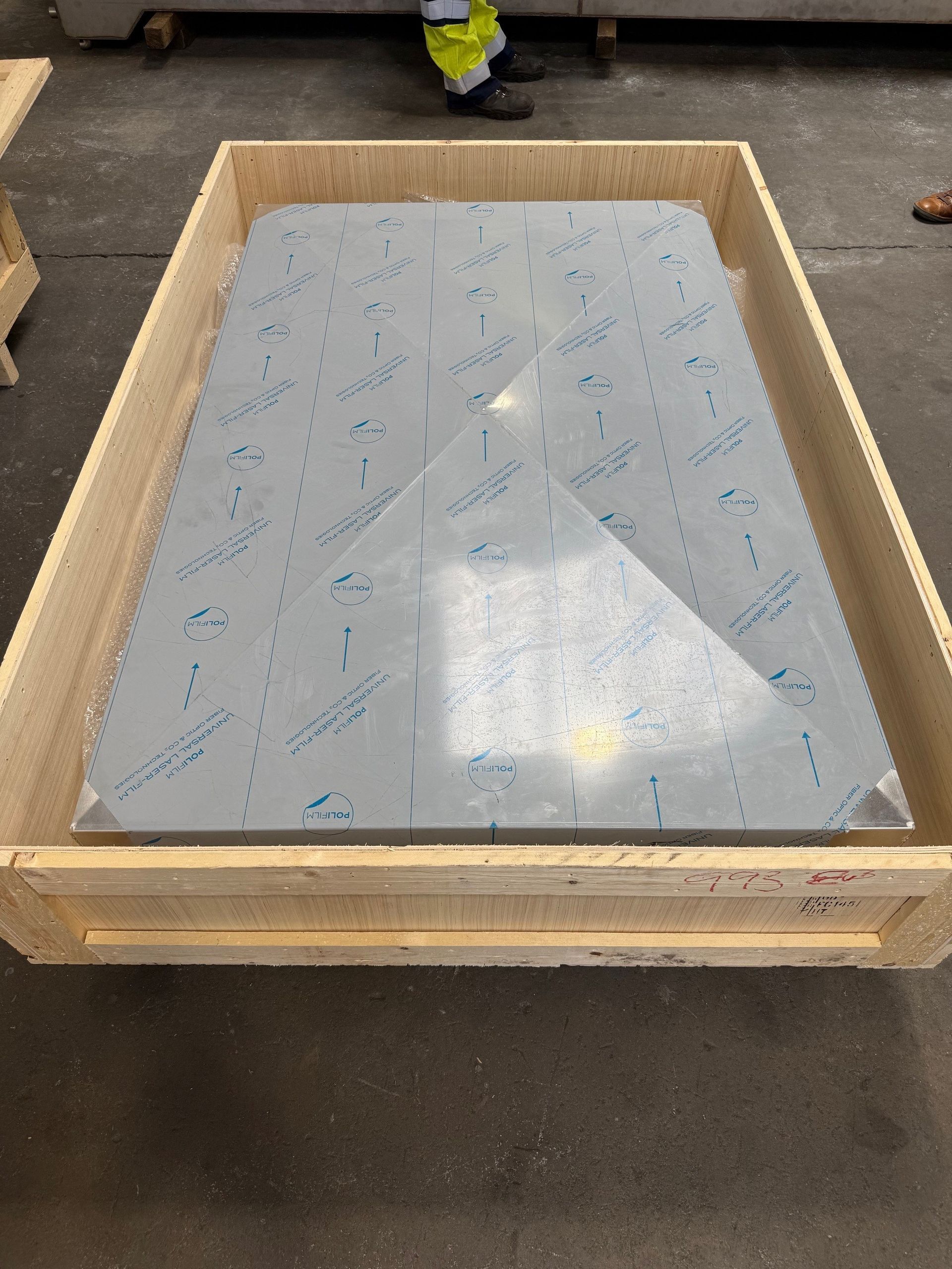
| Supplied in International Shipping Crates for dispatch |
Typical Areas of Application
· Chemical Production
· Petroleum Industry
· Paint, Varnish Manufacturers
· Energy/ Mining Industry
· Co-Generation Plants
· Hydrogen Applications
· Lithium Battery Storage
· Automotive (air bag, mfg. Plant lines)
· Automotive
· Gas/Vapour Handling Equipment
· Dust Collection Systems
· Paper Process (solvent use/storage)
· Grinding/Pulverizing
· Hospitals (gas and/or flammable storage areas)
· Brewery Facilities (grain storage/processing)
· Fossil Fuel Plants (coal dusts)
· Food Processing (airborne dust)
· University Labs (chemical lab store rooms)
· Grain Milling Facilities (airborne dusts)
· Nuclear Power Stations
· Printing Companies (solvent use/storage)
Protecting a Diverse Range of Industries
When it comes to industries that face the threat of internal explosions, the list is surprisingly diverse. Our blast relief roof vents are applicable in various sectors, including the petroleum industry, energy and mining, and even brewery facilities. This wide applicability makes it an essential safety measure across different operational setups.
Automotive plants, co-generation facilities, and lithium battery storage areas also greatly benefit from our specialised roof vents. In environments where safety is paramount, such as hospitals and university laboratories, our vents offer that extra layer of protection that could also be the difference between total collapse and business continuity. This explosion protection helps to mitigate damage to businesses and organisations so that they can get back to operational capacity as quickly as possible.
It may not always possible to include the preferred number or size of other blast mitigation products such as Fixed Blast Louvres, Frangible Blow Out Panels, Hinged Vents and so forth and in those cases, where possible, the inclusion of a Blast Relief Roof Vent is a simple and very effective safety net in such applications.
How Do Our Explosion Relief Vents Work?
Understanding how our blast relief roof vents work is important for optimum utilisation. These roof venting systems function by allowing a lightweight insulated top panel to break free when a pre determined pressure from within the room is applied to them.
The top panel is held in place by ‘FM Approved’ release fixings within a specially designed blast release assembly. The release pressure can also be adjusted to suit the internal blast requirements and also the external climatic conditions. The force of an internal blast is extremely onerous when compared to a free field blast. The top panel is dispelled at extremely high velocities and to try to mitigate further hazards the top panel is tethered with steel cables.
During an explosion, pressure waves and gas waves reflect off walls and fitments, creating elevated pressure levels in various locations within the room or facility. Our roof vents are engineered to mitigate these extreme conditions, making your workspace not just compliant with safety regulations but also a haven of occupational safety. Our engineers have used their years of experience to create pre-fabricated pressure relief vents that are designed to handle these situations. For larger room areas, these roof explosion vent systems can sometimes work better when more than one is utilised, allowing the pressure to be shared, as it is sometimes extremely difficult to determine exactly where peak pressure will emanate.
Roof Vent Assembly Testing
It is important to perform various tests on products to actually see that even when items are certified independently, they work correctly when incorporated into our products. The information or testing that we offer in relation to our products is the basis upon which we supply these to our customers. It is the responsibility of the customer to satisfy themselves as to the suitability of all our products or take independent advice if they feel it is required.
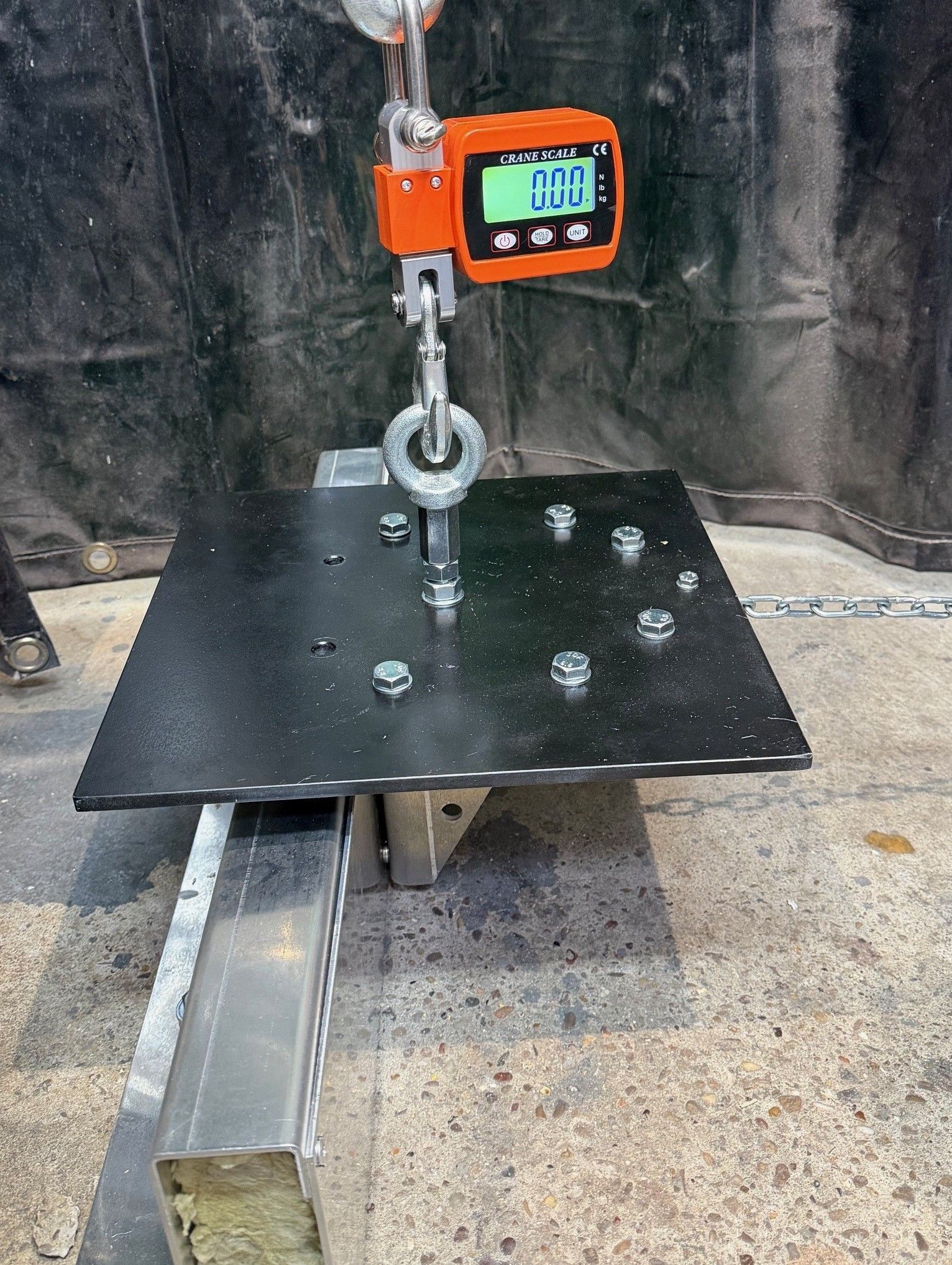
Here is a sample of an FM Approved Blast Release Bolt under test in our Blast Roof Assembly.
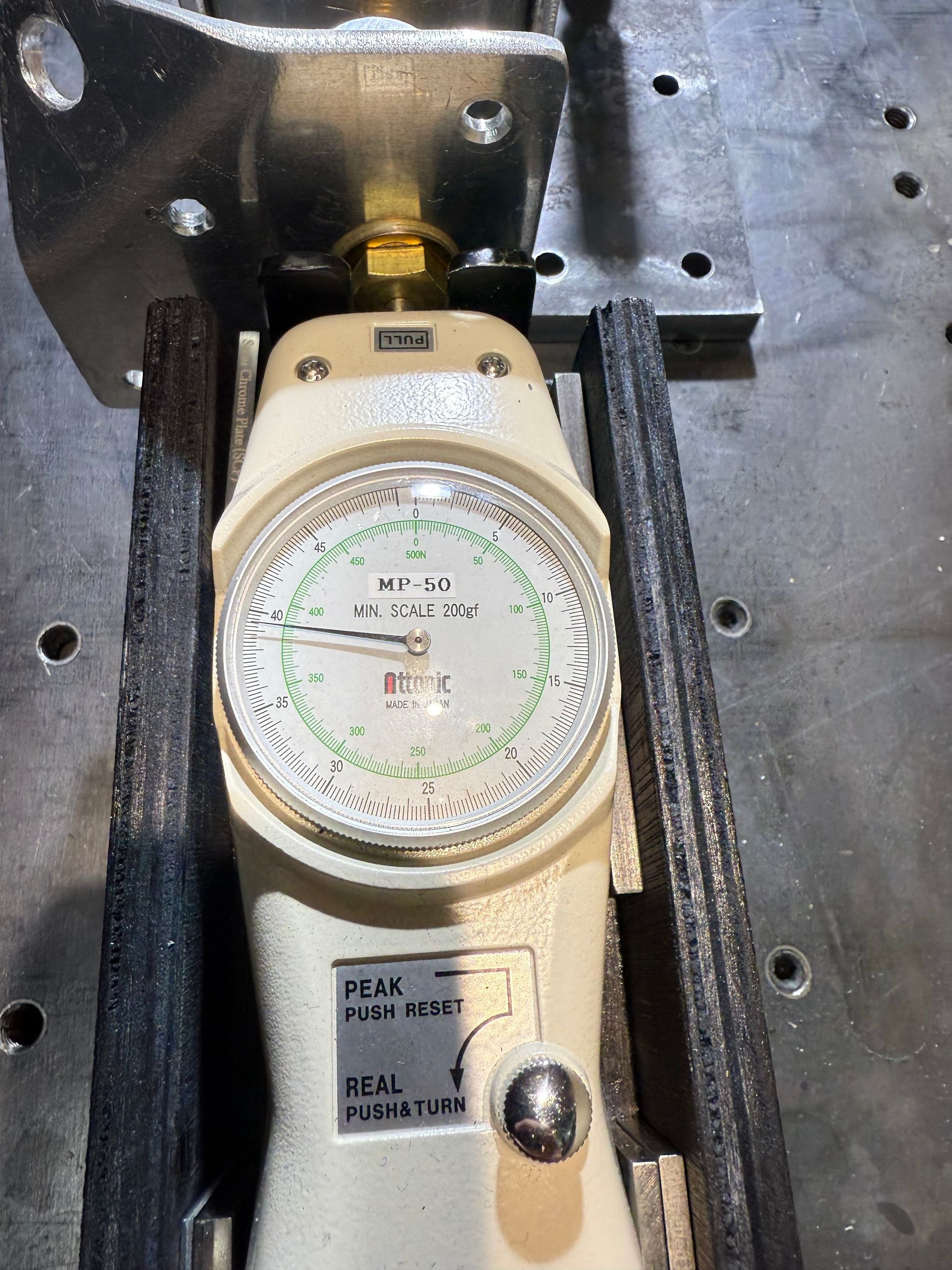
1. Introduction
This report presents the results of load testing carried out on the Blast Roof Vent Release Assembly.
The purpose of this test programme was to:
1. Confirm correct deployment of a FM Approved Vent-All TAN EXA 79 collapsible washer under load, even where structural distortion may occur.
2. Determine the ultimate tensile capacity of the complete release assembly within the Blast Roof Vent using a non-collapsible washer to establish available structural safety margin.
2. Description of Test Specimen
General Arrangement
The tested assembly comprised of:
o Lower half of release assembly integrated into a short section of lower frame wall.
o Lower frame wall bolted directly to a concrete floor slab.
o Upper element fixed to a section of internal roof panel skin.
o Roof panel skin connected to a rigid steel plate.
o Rigid plate connected to a vertical hoist for controlled tensile loading.
o Connection between upper and lower elements via:
o Vent-All TAN EXA 79 collapsible washer (Test 1)
o Non-collapsible washer (Test 2)
This configuration was intentionally selected to produce a slightly more onerous condition than a corner installation, where the structure would normally be more rigid.
3. Test Set-Up
Load was applied vertically using a mechanical hoist at a controlled rate of:
1.2 metres per 8 seconds
Load was measured using an in-line calibrated force meter (displayed in kilograms).
A viewport was incorporated into the test rig to allow:
o Direct visual confirmation of washer deployment
o Simultaneous viewing of force meter reading at moment of release
The full test sequence was recorded on video.
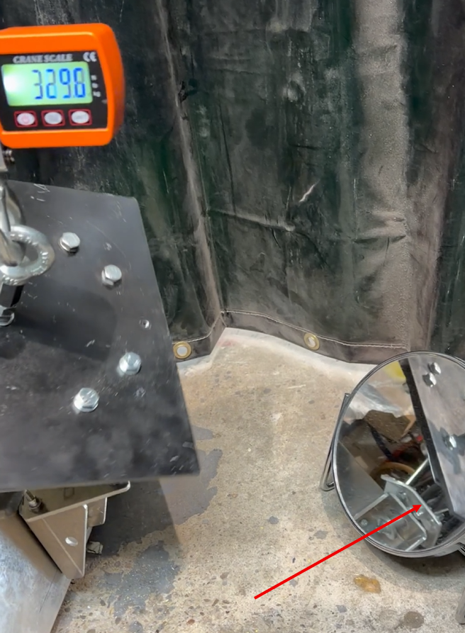
Note: Viewing the release assembly from the side, it is clearly seen that the assembly has reached ultimate load and breaks away at 329.6kg.
4. Test Procedure
1. Assembly installed and aligned.
2. Load applied gradually via vertical hoist.
3. Force monitored continuously on in-line force meter.
4. Deployment visually observed through viewport.
5. Release load recorded at the exact moment of actuation.
6. Entire event captured on video.
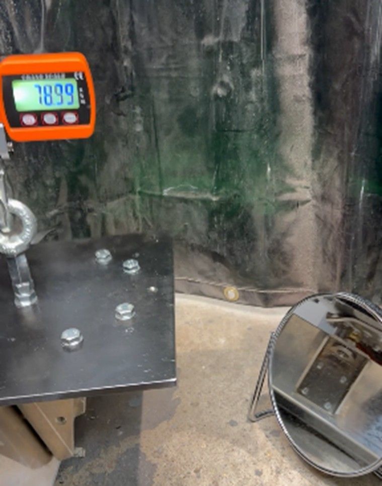
5. Test - FM Approved EXA 79 Collapsible Washer
Objective
To confirm that the EXA 79 washer deploys cleanly and within its design parameters, even where some structural distortion may be present.
Results
Measured Release Load: 78.99 kg
Observations
o Washer deployed cleanly.
o No binding or irregular deformation observed.
o Lower wall section exhibited minor expected movement.
o Deployment occurred in a controlled and predictable manner.
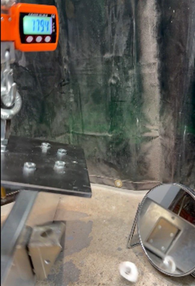
6. Test 2 - Non-Collapsible Washer (Ultimate Strength Test)
Objective
To determine the ultimate yield capacity of:
o The release assembly
o Connections to upper roof panel section
o Connections to lower frame wall section
Results
Failure Load: 329.6 kg
Observations
Failure
7. Analysis
Parameter Value
Controlled Release Load 78.99 kg
Ultimate Failure Load 329.6 kg
Safety Margin Approx. 4.18 : 1
This demonstrates that:
o Controlled release occurs significantly below structural failure.
o The assembly provides substantial reserve capacity.
o The construction allows consideration of alternative collapsible washer types where required.
8. Conclusions
1. The EXA 79 collapsible washer deployed cleanly at 78.99 kg.
2. Structural distortion present in the test configuration did not impede correct operation.
3. The ultimate failure load of 329.6 kg confirms a substantial structural safety margin.
4. The Blast Roof Vent Release Assembly demonstrates robust and predictable performance under tensile loading.
This test was conducted in accordance with internal procedures and recorded on video. The results stated in this report relate only to the specimen tested.
What is Quasi-Static Testing of a Dynamic Blast Relief Device
The Blast Roof Vent is designed to relieve internal overpressure generated by an explosion event. Such events are dynamic in nature, typically involving rapid pressure rise and transient fluid–structure interaction effects.
However, the release mechanism within the Blast Roof Vent assembly — specifically the calibrated collapsible washer — is fundamentally a force-activated mechanical device. Its deployment is governed primarily by:
o Material yielding characteristics
o Geometric deformation behaviour
o Tensile force magnitude
It is not dependent upon impact acceleration, inertia, or strain-rate-sensitive triggering mechanisms.
For this reason, validation of the release assembly was conducted under controlled quasi-static tensile loading conditions. Quasi-static loading refers to the application of load at a sufficiently slow rate such that:
o Inertial effects are negligible
o The structure remains in near mechanical equilibrium throughout loading
o Measured force corresponds directly to material and connection strength
Testing under quasi-static conditions provides several engineering advantages:
- Accurate determination of calibrated release force
The measured deployment load represents the true mechanical threshold of the washer without dynamic amplification effects. - Clear observation of deformation mode
Controlled loading allows verification that the washer deploys cleanly and without binding, even where minor distortion is present. - Establishment of structural safety margin
Ultimate yield testing under quasi-static conditions isolates the intrinsic capacity of the assembly and its connections.
While the operational environment of a blast roof vent involves dynamic pressure loading, the quasi-static test method is appropriate and standard engineering practice for verifying the calibrated mechanical release characteristics of force-governed components.
Ballistic Protection
Describe some quality or feature of the company. Write a short paragraph about it and choose an appropriate icon.
Blast & Ballistic Venting Products
Describe some quality or feature of the company. Write a short paragraph about it and choose an appropriate icon.
What does ‘FM Approved’ mean?
FM Approvals is an international leader in third-party testing and certification services. We test property loss prevention products and services—for use in commercial and industrial facilities—to verify they meet rigorous loss prevention standards of quality, technical integrity and performance. How? By employing a worldwide certification process that’s backed by scientific research and testing, and over a century of experience.
The FM APPROVED mark is recognized and respected worldwide. Our certification instils confidence and commands respect in your marketplace. Read more about
FM Approval Guide
here.
Why Choose Blast & Ballistics?
Choosing Blast & Ballistics for your blast relief roof vents means opting for quality, reliability, and above all, safety. Our commitment to delivering specialist blast and safety products is backed by testing and years of industry experience. By integrating our roof vents into your safety protocols, you're taking a significant step towards making your facility explosion resistant. When contacting us, you also have a wide range of products to choose from, ensuring you can fulfil every need and a depth of knowledge that is available to discuss your requirements at all technical levels.
We understand that every industry is unique and comes with its own set of challenges. With all Blast & Ballistics products, you're not just buying a product but also investing in peace of mind.
The Benefits Of Using Blast Relief Roof Vents
When it comes to safeguarding your facility from the risks associated with internal explosions, blast relief roof vents offer an array of benefits beyond basic compliance with safety regulations. These venting systems release pressure vents and products are crucial to your overall safety plan, offering multi-faceted advantages that protect your property and the people within it.
One of the primary benefits of installing our blast relief roof vents is the immediate enhancement of occupational safety. By providing a secure means for pressure and gas waves to escape during an explosion, these vents significantly reduce the potential for structural damage and harm to employees. This helps you maintain business continuity, even in the face of unexpected incidents, by minimising downtime and potential repair costs.
Another overlooked benefit is the potential for lower insurance premiums. By demonstrating that your facility is equipped with state-of-the-art safety features like our blast relief roof vents, you may qualify for preferred insurance rates. This means that your investment in safety could lead to long-term financial benefits for your business.
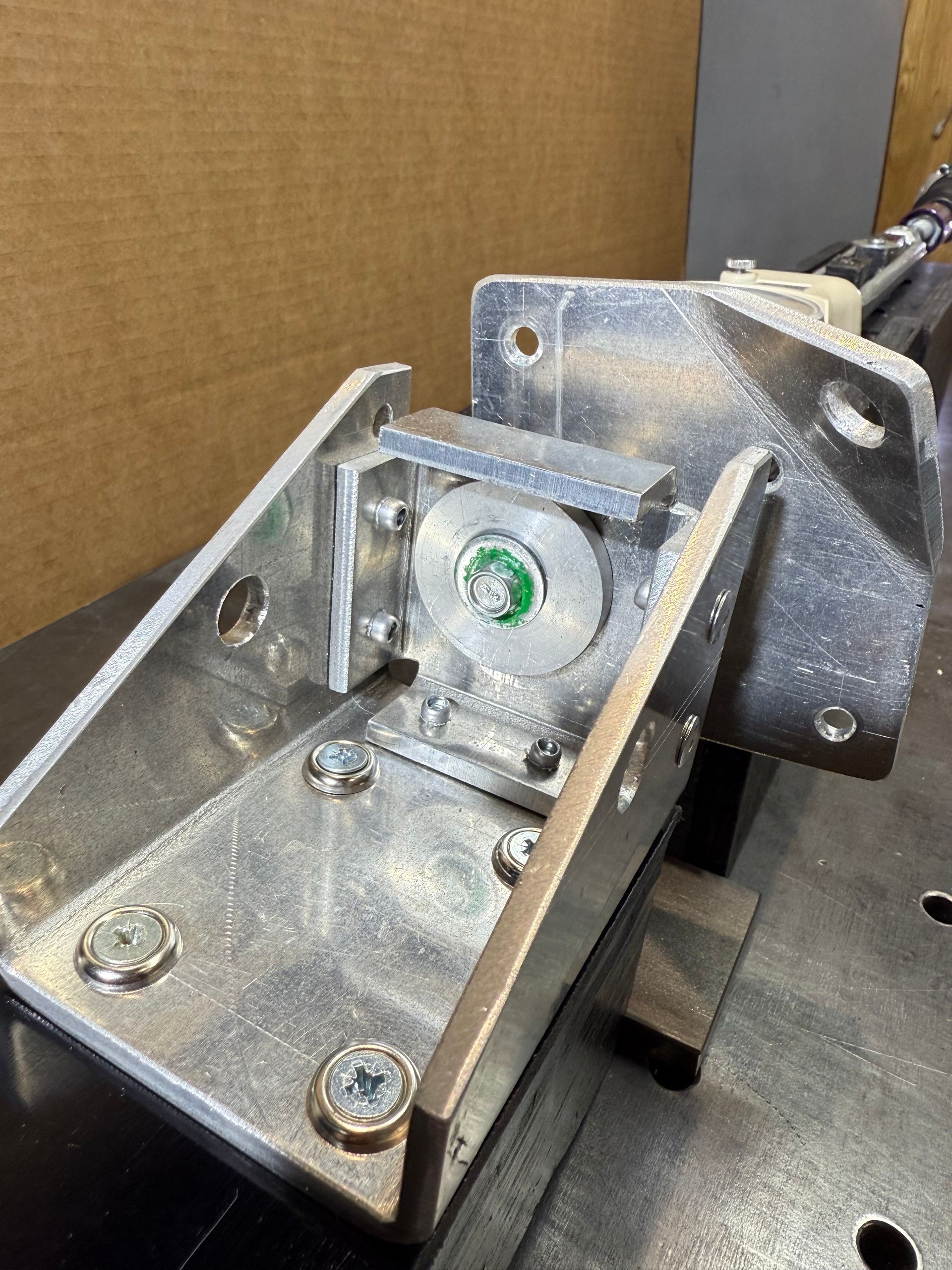
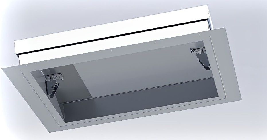
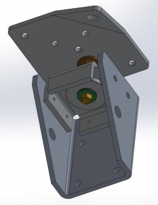
See how the Individual Components of the Roof Vent Work Together
FM Approved Blast Release Bolts
FM Global (Factory Mutual Insurance Company) has underwritten a wide range of Blast and Explosion Mitigation products. This product is constructed to those guidelines see – FM Global Property Loss Prevention Data Sheet 1-44 sub section 2.1.4 Pressure Relieving Vent Panels.
In addition, all explosion release bolts are fully FM Approved and provide a range of release values for this safety product.
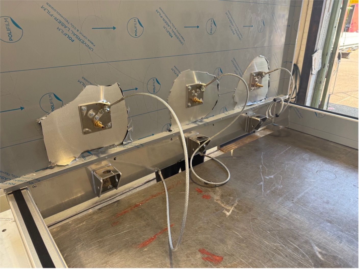
Release assembly units and FM Approved Release Bolts are positioned internally and are easily accessible for maintenance or adjusting the release requirements.
All venting systems rely to the greater extent on an equal balance of pressure across its surface for optimum performance. This is important to keep in mind because not all explosions can be so predictable. Internal explosions are notoriously difficult to determine because there is a pressure wave and a gas wave that reflect around internally off the walls and other fitments and in doing so create elevated levels of pressure in various locations.
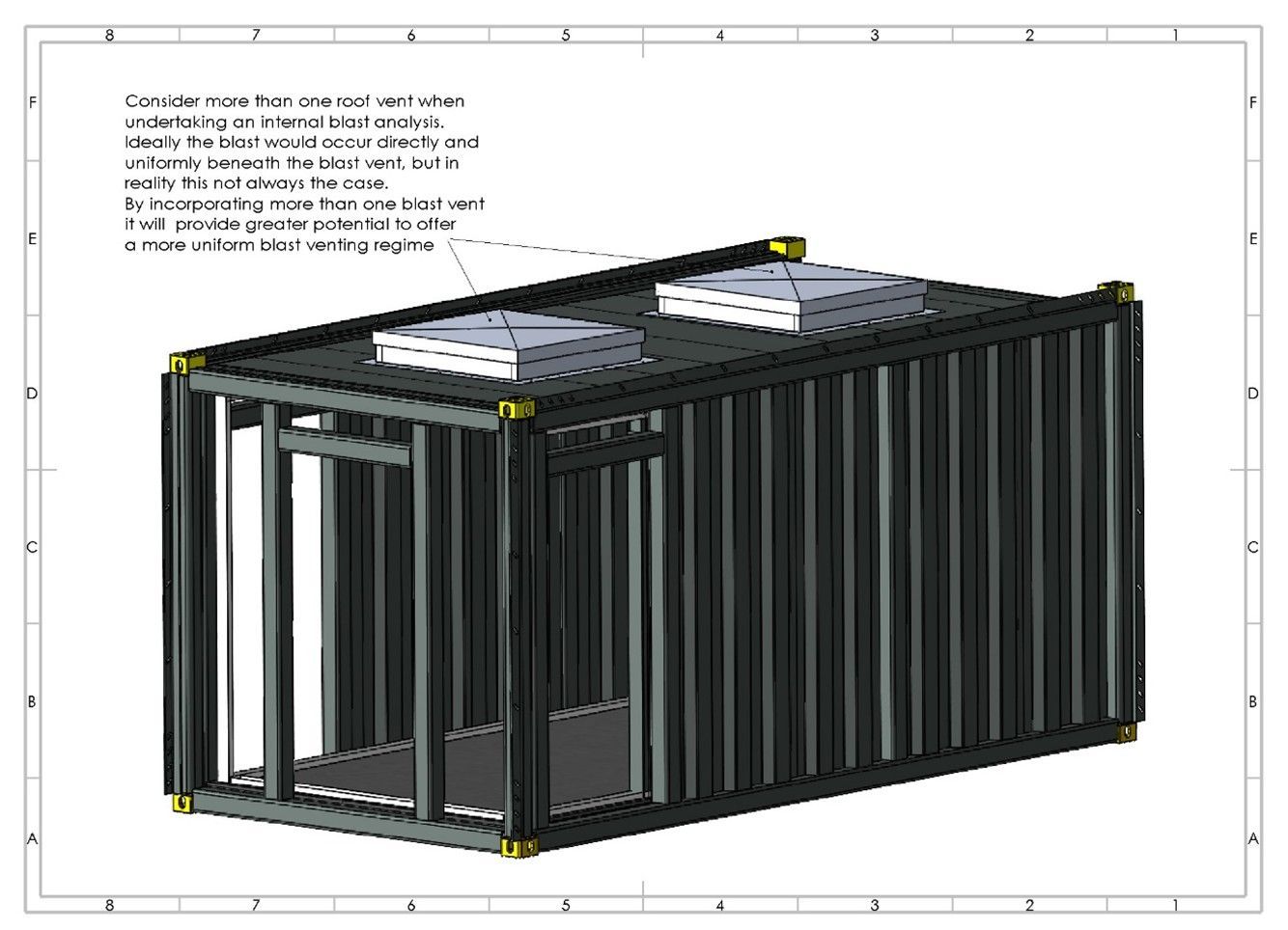
Consider more than one roof vent when undertaking an internal blast analysis. Ideally the blast would occur directly and uniformly beneath the blast vent, but in reality, this is not always the case. By incorporating more than one blast vent it will provide greater potential to offer a more uniform and even blast regime within the building.
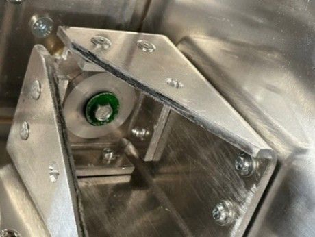

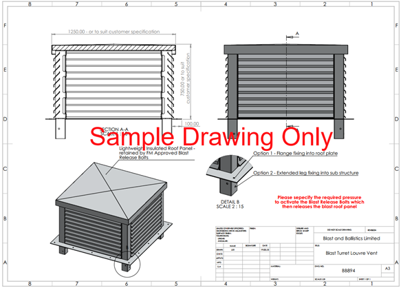
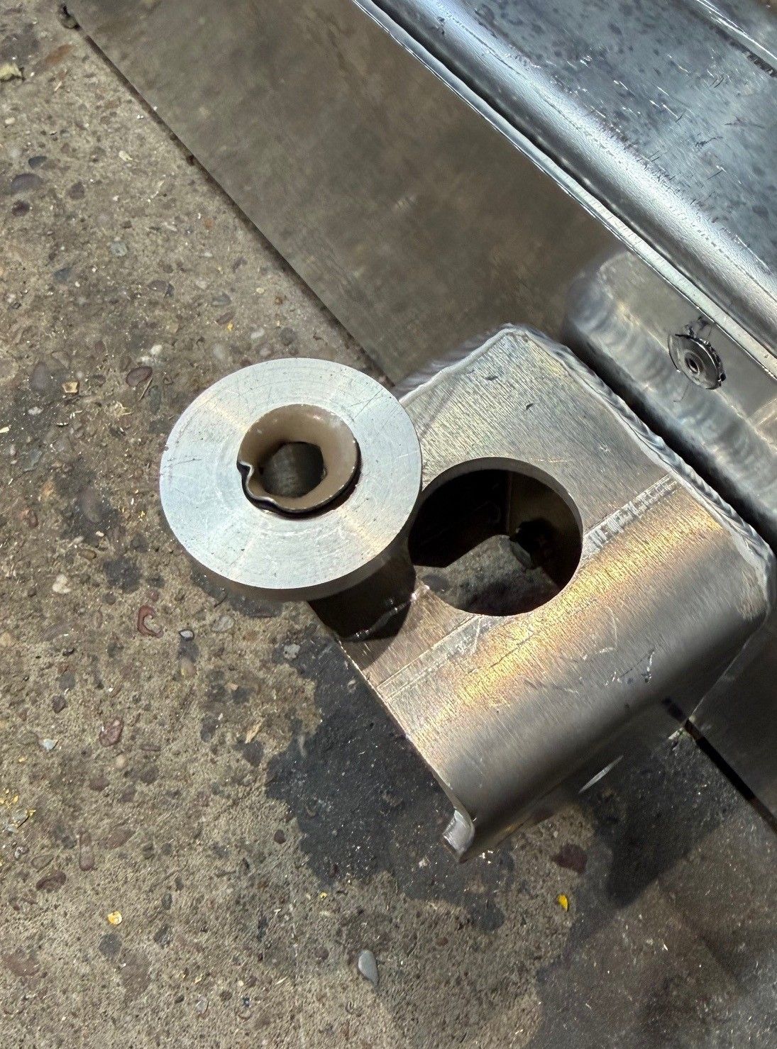
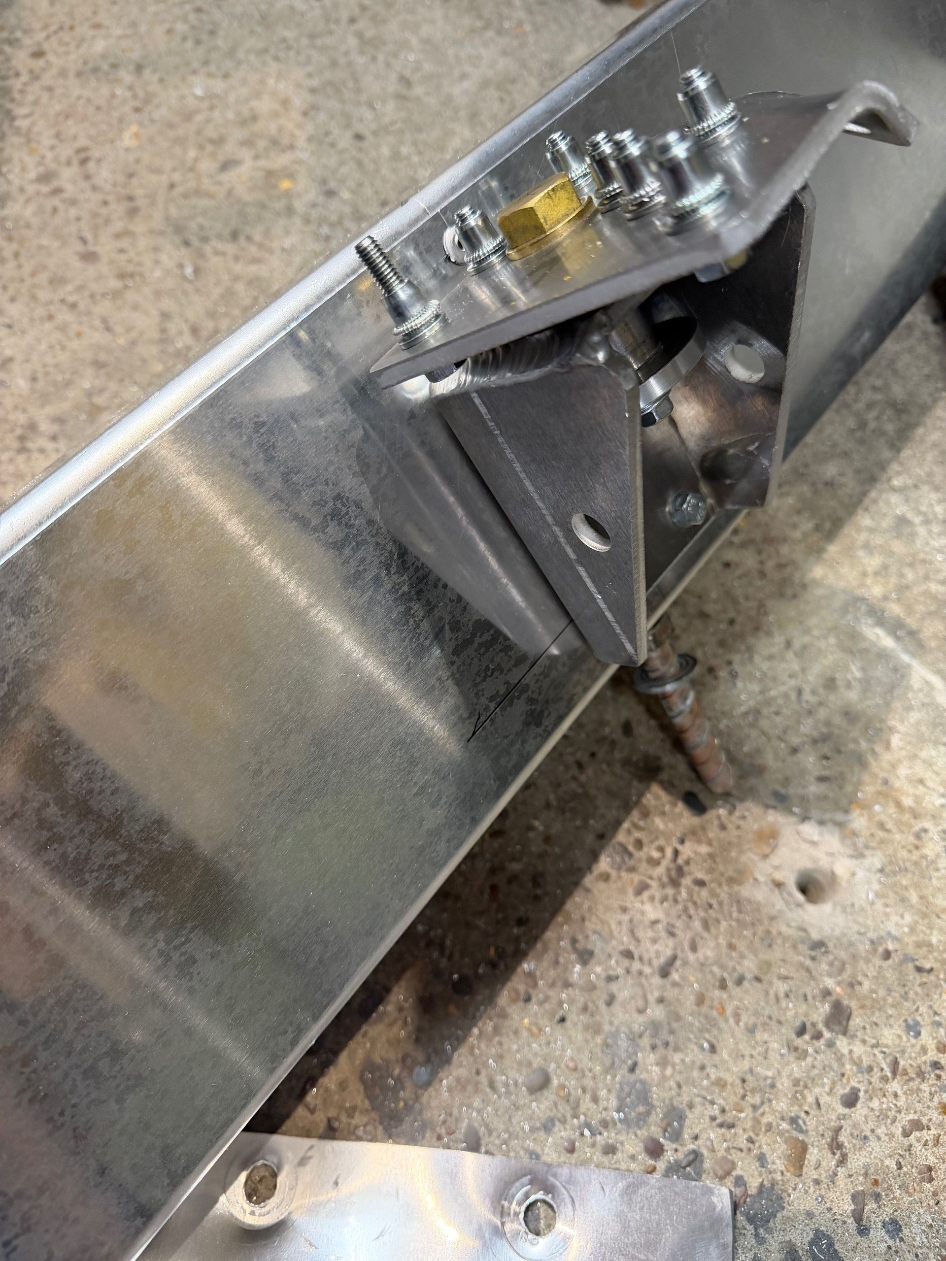
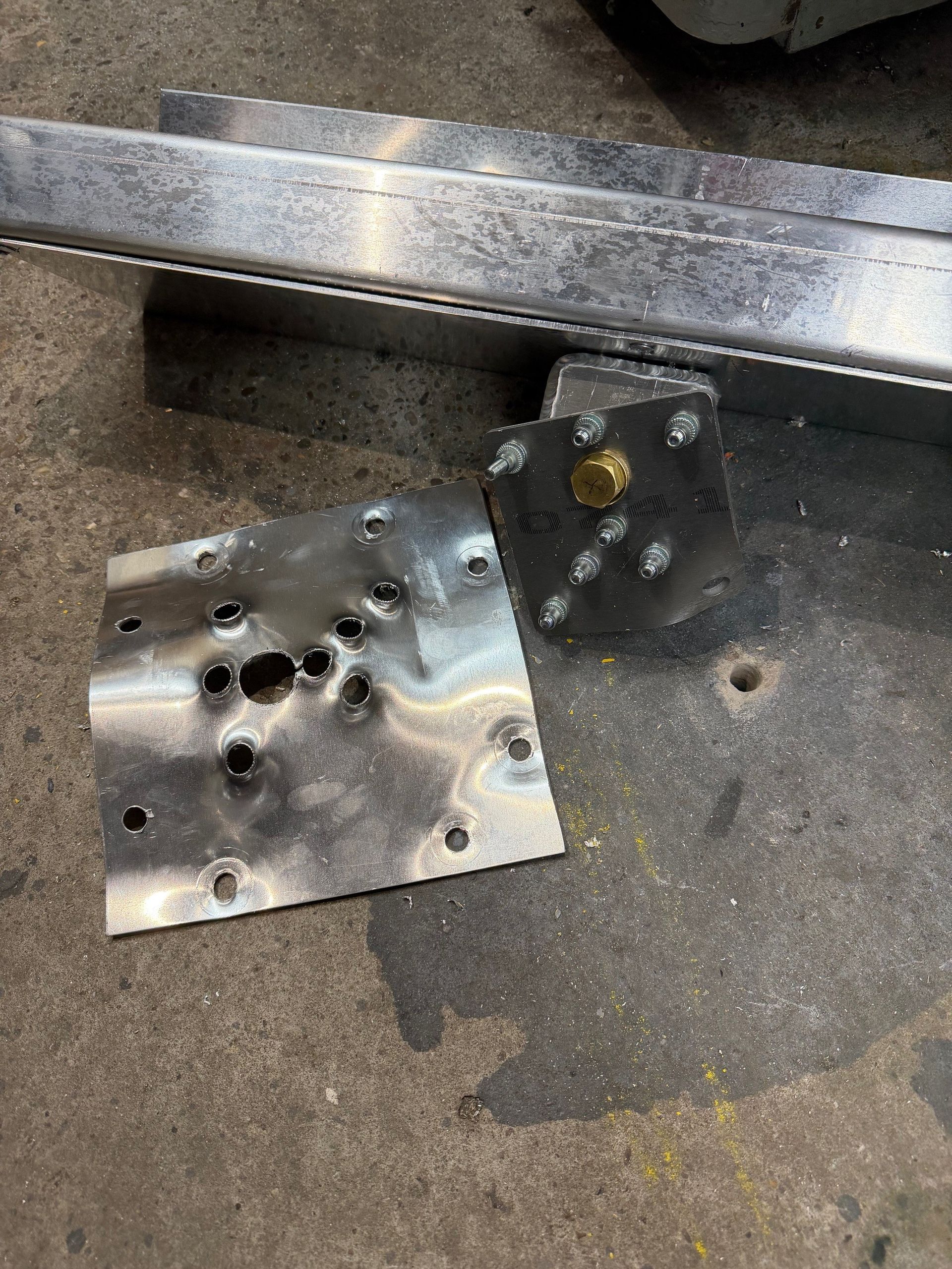
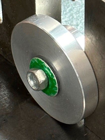
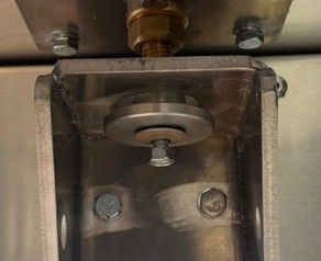
Release Assembly Unit
The Release Assembly Units hold the lightweight roof panel in place. The large washer that also contains the special FM Approved release bolts, is designed to move within the assembly to allow for heat expansion of the roof panel. All of these components are supplied factory assembled but note how the release washers should appear when correctly tightened or if the panel needs to be removed and replaced at some point in the future.
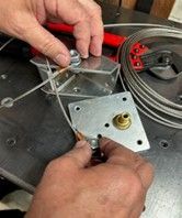
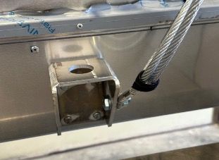
The Vent Assemblies are fitted with steel cables to mitigate the potential for the lightweight roof panel to break away from the confines of the building should the unit need to be deployed following an internal blast or explosion.
Additional Information
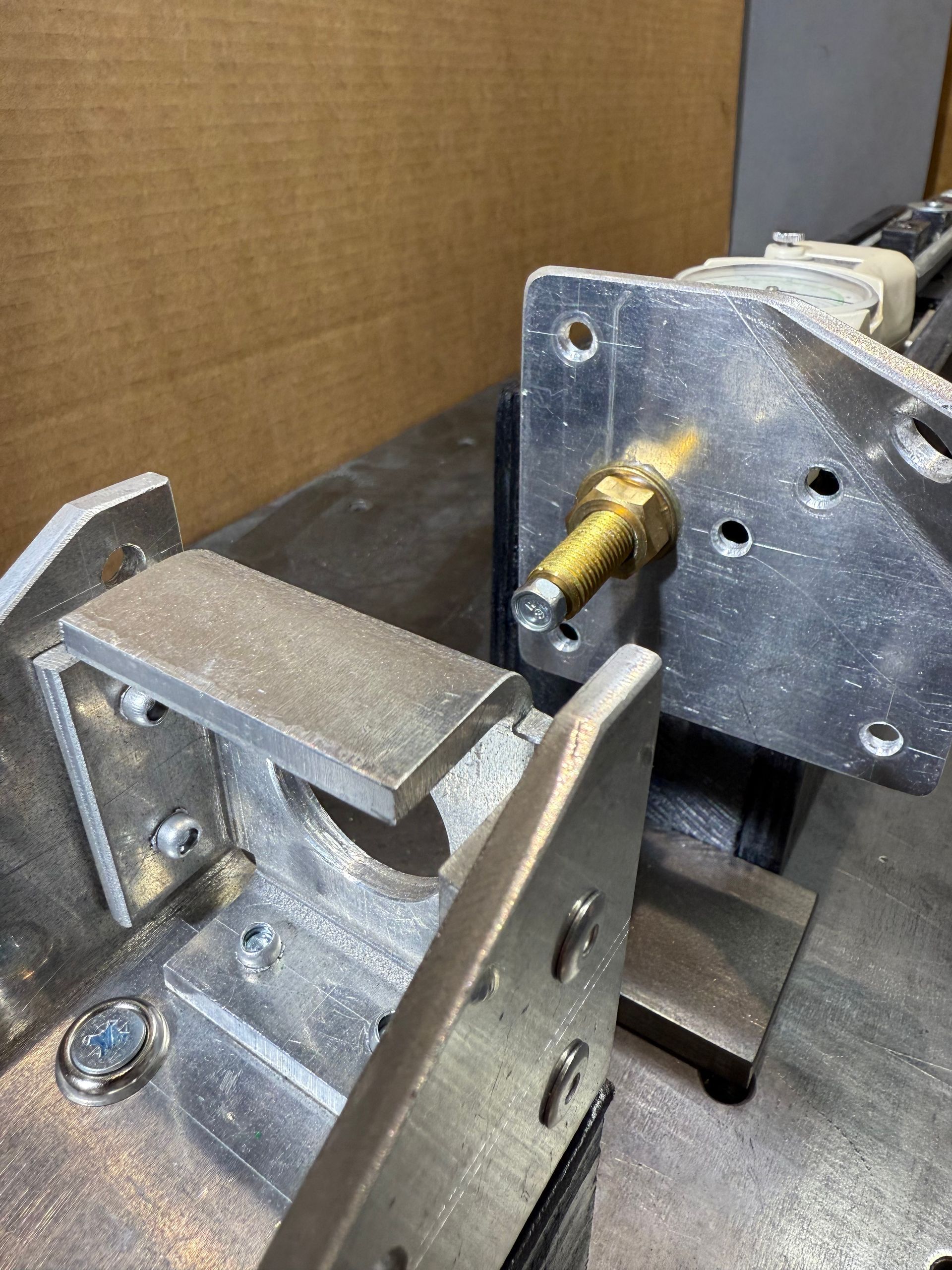
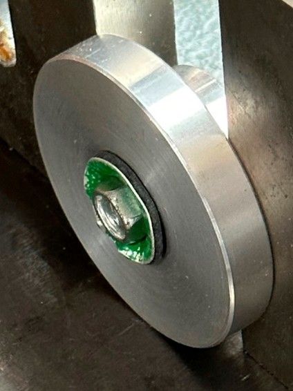
Removing & Inserting the Special Release Bolts
It may be necessary to remove and replace the special release bolts that are supplied with this product. This may be because the roof panel has been removed during installation, or when doing so the bolt was overtightened and deformed prematurely (see images on page 6). Conversely, it may simply be the case that the release value of the bolts supplied may need to be changed for those offering a different release value to accommodate a change in the buildings blast regime
FM Approved Release Bolts
FM Approved Release Bolts are globally recognised in the industry and provide you with the certified performance and required credibility to meet international standards.
This ensures consistency in each product and reduces the risk of incorrect activation.
Note: The special release bolt supplied with the release washer as shown left, fits into a pre-threaded hole. This is a coarse thread and may initially feel difficult to start. When correctly aligned however it can be easily inserted by hand. DO NOT FORCE THIS BOLT INTO THE PRE THREADED HOLE.
Click here to see a video of this: https://www.youtube.com/shorts/q_ux6eO6bEI
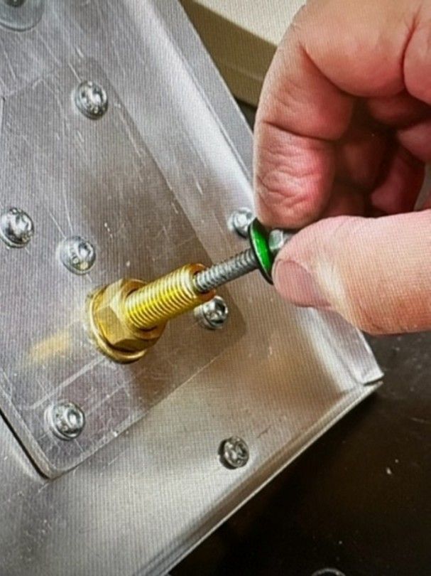
Expansion & Contraction of the Roof Panel
Expansion Washer – This is the large washer that is fitted into the release assembly and through which the release bolt passes. When correctly tightened, the release bolt and washer should appear as in this picture (left) and the washer should be free to move around as shown in the accompanying video.
When roof panels are fitted onto the roof of buildings they are immediately exposed to all elements of weather. One of these being direct sunlight. This can cause the roof panel to expand and contract and in order to mitigate applying a sidewards loading on to the release fixing, this washer will move with the roof panel but still keep the release bolt aligned.
Click here to see a video of this:
https://www.youtube.com/shorts/qPo_lBG30c8
Understanding the Release Assembly
A short video clip showing the release assembly working can be seen by clicking on the following link. It is worthwhile looking at this and gaining an understanding of what happens during the release process.
Under blast loading this all happens in milliseconds but the link below shows the operation taking place under controlled conditions and much more slowly. Note carefully at the midpoint of the video, the green collapsible washer can be seen to deform momentarily and then the force is re applied to demonstrate the bolt head travelling through the washer and releasing the assembly.
Click here to see a video of this: https://www.youtube.com/shorts/TNeSzGO1LTQ
Damage-Limiting Construction
Global Property Loss Prevention Data Sheets 1-44, Extract with reference to Roof Vent Panels and FM Approved Release Fasteners
2.1.3 Location
2.1.3.1 Locate rooms or buildings requiring damage-limiting construction in accordance with Section 3.1.1.
2.1.3.2 Avoid venting a single end of an elongated enclosure. Where this situation is unavoidable, follow the guidelines in Section 3.1.7.
2.1.4 Pressure Relieving Vent Panels
Install at least a total area of pressure relieving vent panels that equals the minimum recommended vent area.
Do not credit roof vent panel areas subject to accumulation of snow, ponded water, dust, or debris.
Where this situation is unavoidable, refer to Section 3.1.2. A maximum weight of 3lb/ft2 (14.6kg/m2) is generally recommended for venting roof panels.
2.1.4.1 FM Approved Products
Follow the manufacturer’s instructions for the installation of FM Approved (see Appendix A for definition) explosion venting systems, including fasteners and washers.
The following recommendations apply to the installation of FM Approved explosion venting systems including fasteners and washers:
1.When FM Approved, collapsing washers are used, a1⁄2in. (13mm) diameter oversized hole should be drilled in the wall panel and a slightly smaller diameter centering washer or sleeve should be installed. It is imperative that the pilot hole for the screw/bolt be centred with respect to the centering washer. Only a specifically FM Approved No.14 (1⁄4in., 6mm in diameter) screw/bolt should be used with this washer (seeFigure2.1.4.1-1).
©2000-2023 Factory Mutual Insurance Company. All rights reserved.
Vent-All FM Certified Approved Release Washers identification colours –
EXA-74 Colour Code GREEN Release Value Per Fastener 70# / 0.31 kN
EXA-76 Colour Code BLUE Release Value Per Fastener 110# / 0.49 kN
EXA-79 Colour Code TAN Release Value Per Fastener 175# / 0.78 kN
EXA-84 Colour Code LIGHT GREEN Release Value Per Fastener 435# / 1.93 kN
Release calculations of venting panel in this product include the weight of the roof panel e.g. –
Weight of roof panel in kN + 2 x Vent Washer in kN /vent area
The illustrated Release Washer in this Data Sheet is GREEN, release value 70lbs/0.31kN
The Release Assemblies are fitted centrally and opposing to balance the resistance of the Roof Panel
Applications that require 4 No. Release Assemblies are also paired about centre
Imbalanced blast waves can cause distortion and compromise operation. Keep Roof Panels clear of debris and snow accumulation at all times. An excessive internal explosion could compromise the restraint cables and also distort the roof panel requiring replacement before future use.
Note – As noted above, these roof vents have facility to accommodate movement within the roof panel when exposed to temperature variations. However, without maintenance/inspection, problems can occur due to inadvertent releases from wind, expansion and contraction caused by temperature changes, maintenance personnel walking on the roof, and even heavy equipment vibrations from inside the building. Snow & ice and other debris on the roof may delay or prevent release.
Any roof vent will always require maintenance/inspection. The FM Approved release bolts are a standard and universal blast release product. The FM Approved release bolt does not guarantee complete performance in all instances. Again reiterating the importance of regular maintenance and inspections.
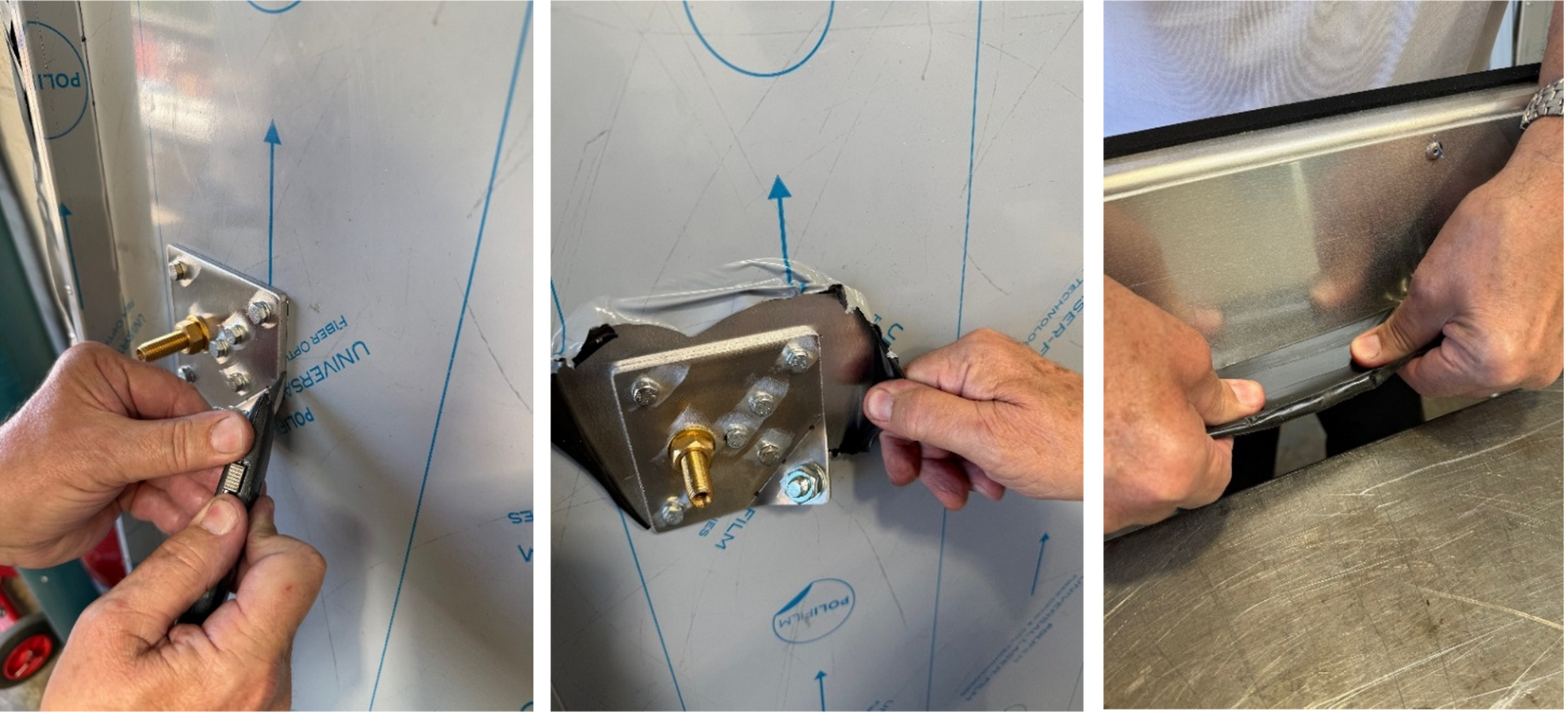
Installation Instructions
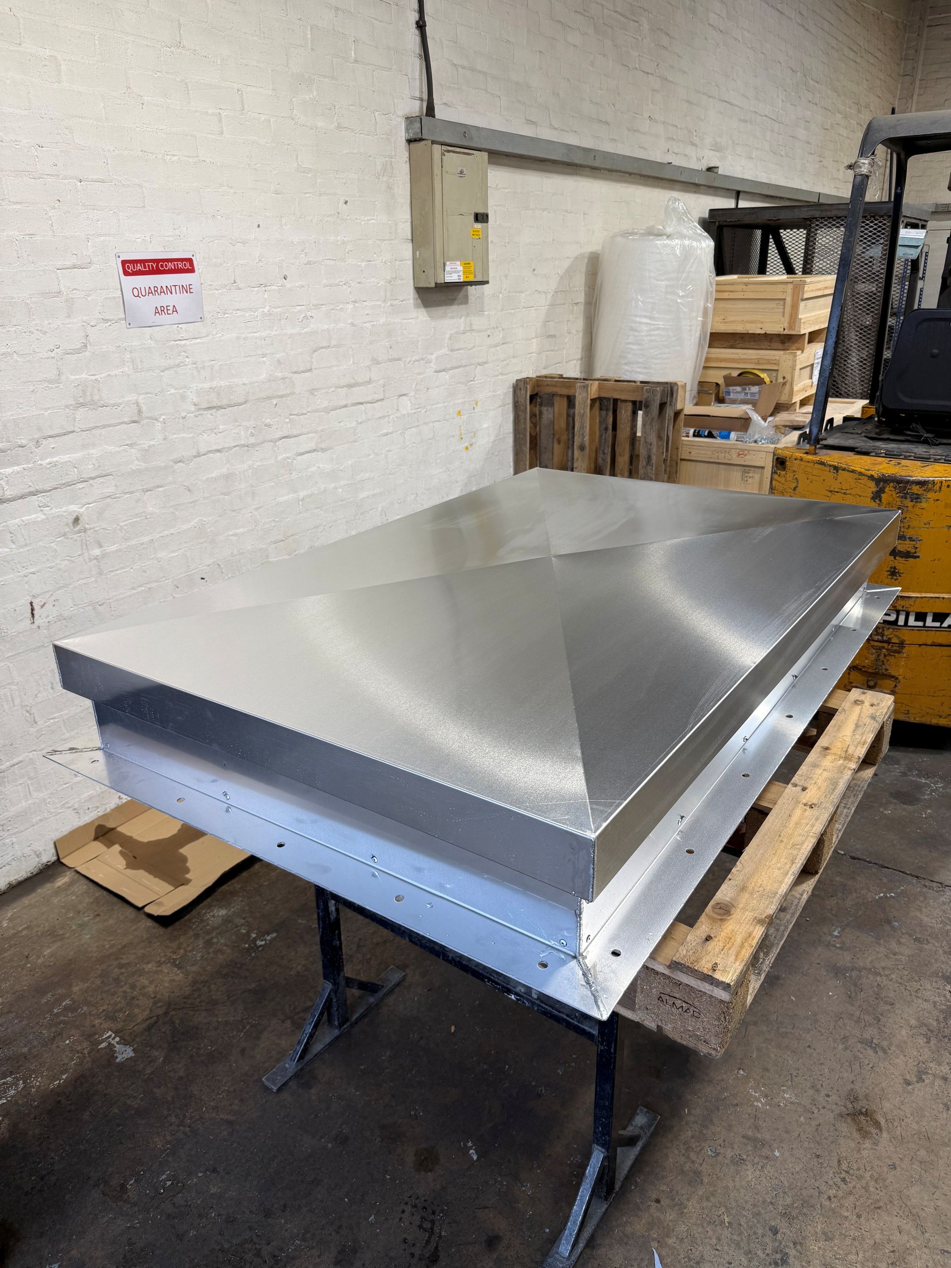
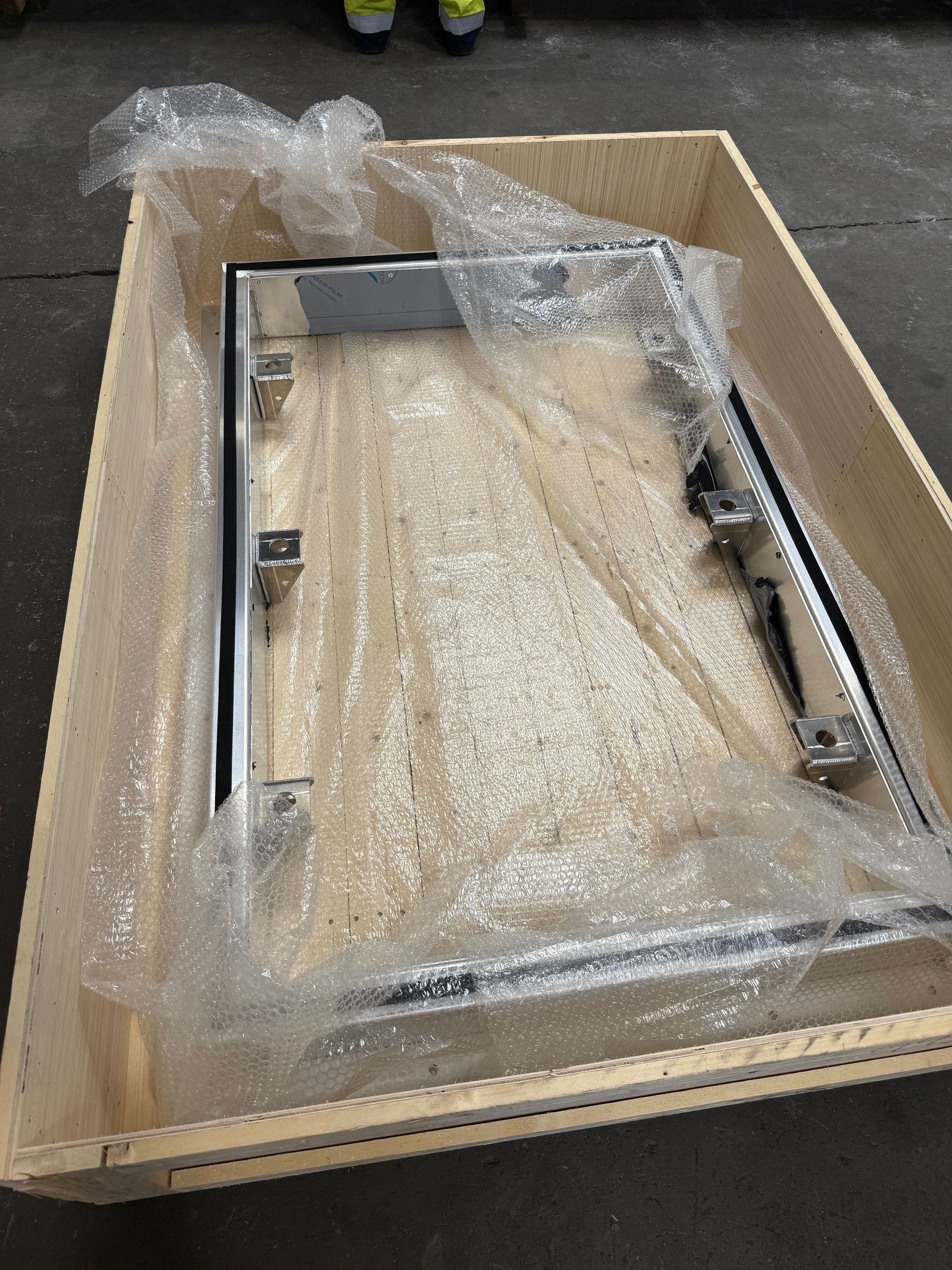
1. The roof vents are delivered to site in timber crates. The roof vent will have a protective wrapping for convenience when installing and should be removed when the installation is complete.
2. Carefully remove the roof vent lid and set aside. In the crate will be the lower half of the roof vent, that is the vertical sides and the flange will bolts down to the roof.
3. Position the roof vent over the pre-prepared aperture in the roof of the building.
4. When satisfied that it is in the correct position, remove the lid of the vent once again and drill the fixing holes into the roof in order to bolt the flange down.
Remove the flange and lower half of the assembly. Clean away all dust and debris thoroughly and then use a proprietary sealant or similar so that when the lower half of the assembly is once again repositioned and bolted down, it provides a water-tight seal.
Final Assembly of the Roof Vent
There are two suggested methods to connect the top roof panel to the lower part of the assembly.
Option 1
Bolt down the lower half of the assembly. Place the top roof panel on to it and then from inside the building, insert the special connecting bolts to secure the top roof vent panel.
Option 2
After drilling all fixing holes in the roof, the top and bottom parts of the roof vent can be assembled before re-positioning and bolting down to the roof. If the roof vent assembly is fully assembled as in this option, then it must be handled very carefully when placing back into position so as not to disrupt the FM Approved Blast Release Bolts.
Installing the FM Approved Blast Release Bolts (Applicable to both options above)
Connecting bolts on top panel of roof vent shown left
Holes in release bolt assembly – lower half of vent shown left
The roof vent assembly can be fitted with either two, four, six or more release bolt assemblies.
When the lid is placed onto the bottom half of the unit, ensure that the bolts as shown above fall into the holes as shown right.
FM Approved Release Bolt screws up into the connecting bolt on the top panel of roof vent.
It is very important to assemble the release bolt, special washer and aligning bush in the correct order. Tighten the bolt with hand tools only. DO NOT USE POWER TOOLS.
The special FM Approved Blast Release Bolts will have been previously fitted in the factory and therefore it will insert very easily if aligned correctly. If the release bolt cannot be inserted easily, then do not attempt to force this but simply remove it and realign it carefully.
See video:
https://youtu.be/t1QJKbZVuyY
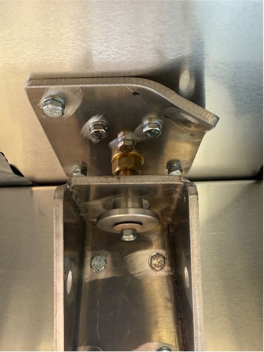
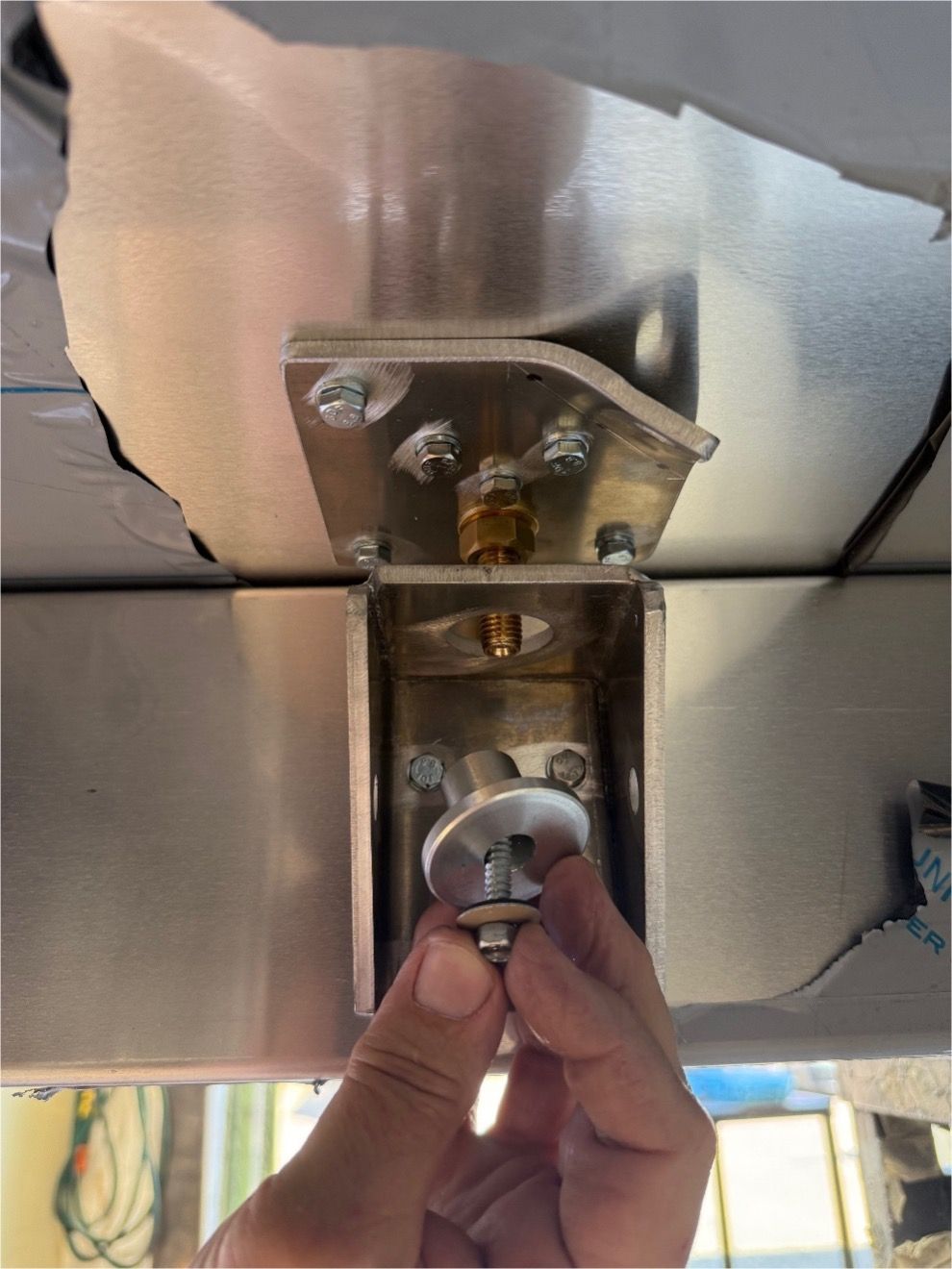
Note: The FM Approved Washer is fragile and is designed to collapse under a pre-determined pressure. Do not overtighten or distort this washer.
Finally, tighten the connecting bolt using hand tools only. DO NOT SQUASH THE SPECIAL RELEASE WASHER.
Attaching the Restraint Cables
Along one side of the roof vent, attach the cables as shown below.
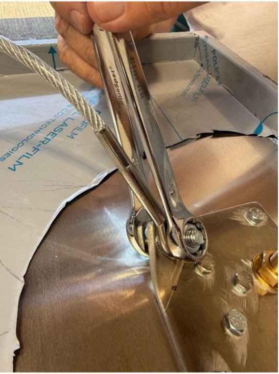
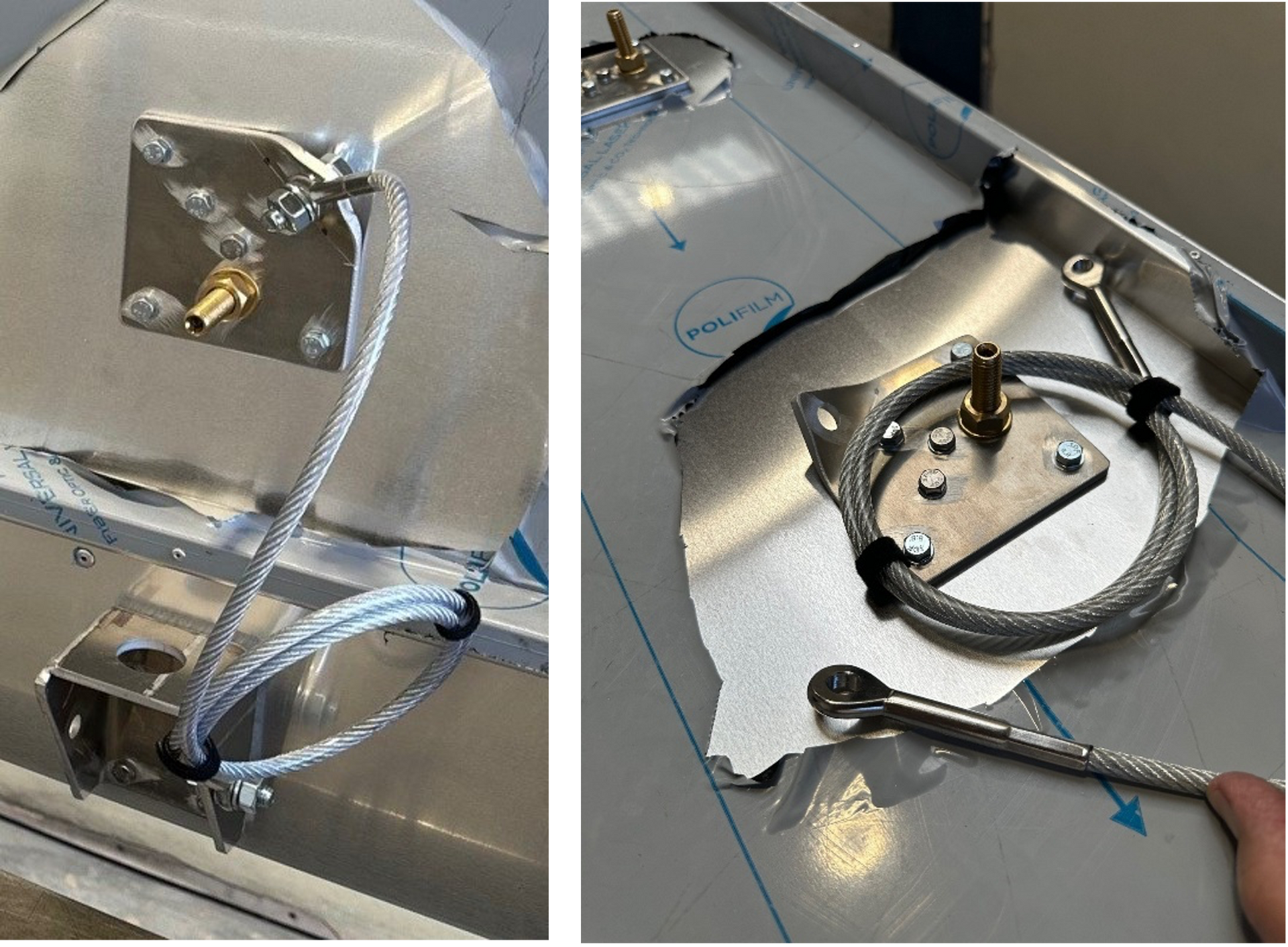
Neatly arrange the cable as shown and lightly hold in place using hook and loop tape fastener, sometimes referred to as ‘Velcro’. Carefully consider how the cable is folded – ensure that it does not get caught up or trapped around any of the release components when it needs to be released.
IMPORTANT – Do not over secure the cable. It must unfurl if the lid is deployed.
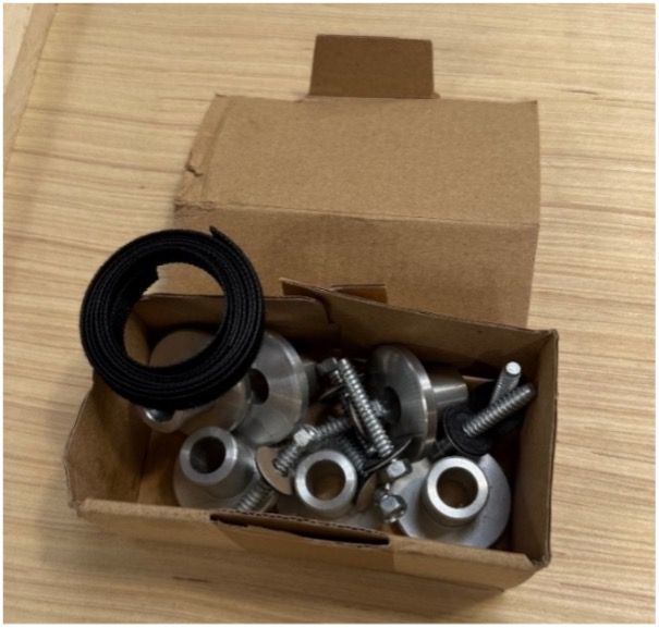
All nuts, bolts, assemblies, washers and fastener provided.
Frequently Asked Questions
Do Blast Relief Roof Vents require regular maintenance?
While our roof vents are designed for durability, as with all safety products, maintenance is recommended to ensure their effectiveness. This is predominantly inspection based more so than actual removal and replacement of parts.
Care must be taken in locations and environments where snowfall may rest on the roof vent and impact the release.
What materials are used in the construction of the vents?
Our Blast Relief Roof Vents are primarily manufactured from aluminium in their construction.
The FM Approved Blast Release Bolts are manufactured from stainless steel with an aluminium alloy washer bonded to an EPDM washer.
What size units are available?
The product is bespoke and made to order, specific to customer dimensions, release values, roof construction and other requirements.
Typically, a larger unit would accomodate a 1000mm x 2000mm open area and a smaller unit would accomodate a 500mm x 500mm area.
The curb height / vertical wall height can also be adjusted if required.
Numerous Roof Vents may be required rather than one large unit to provide an effective and consistent release should an event occur.
Please contact our office for further information.
